


Relative motion and connector parameters can be modified from the Translational Joint property dialog as shown in the figure below. Relative motion parameters such as translational motion and initial conditions are defined in the table that follows. User Subroutines are explained in Motion User Subroutine.
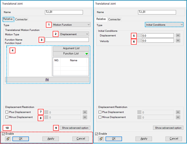
Figure 5.35: Description of Relative parameters in the Translational Joint property dialog
| Parameter | Symbol | Description | Dimension (Range) |
| 1. Type | N/A | Use to select a type of relative motion. When the type is , you can add translational motion to the joint. When the type is , you can apply initial conditions to the joint. When the type is , you can add the translational motion as a user subroutine. | N/A |
| 2. Motion Type | N/A | Use to select the level of the constraint. When the type is , the relative displacement between the two markers is restricted to the specified function. When the type is , the relative velocity between the two markers is restricted to the specified function. When the type is , the relative acceleration between the two markers is restricted to the specified function. | N/A |
| 3. Function Name | N/A | Use to set the name of the function expression. |
N/A (Character) |
| 4. Function Input |

| Use to set the function for the translational motion. It is possible to set one of pre-defined function expressions. For more information, refer to Function Expression. |
Length (Real) |
| 5. Displacement |

| Use to set the initial relative displacement between the two markers. | Length (Real) |
| 6. Velocity |

| Use to set the initial velocity between the two markers. |
Length/Time (Real) |
| 7. Plus Displacement | N/A | Use to set the maximum relative displacement. If this option is selected, it restricts the relative displacement of the joint to less than the specified value. |
Length (Real) |
| 8. Minus Displacement | N/A | Use to set the minimum relative displacement. If this option is selected, it restricts the relative displacement of the joint to be more than the specified value. |
Length (Real) |
| 9. Show advanced option | N/A | Use to show Advance tab. | N/A |
| 10. Control buttons | N/A | If all necessary parameters are set, these buttons are enabled. For more information about the control buttons, refer to Entity Properties Access and Modification. | N/A |
Information about connector parameters can be found in Constraint Entity Connectors.
Friction parameters are defined as shown in the figure and table below. For more information on their usage, refer to Friction in a Translational Joint in the Motion Theory Reference.
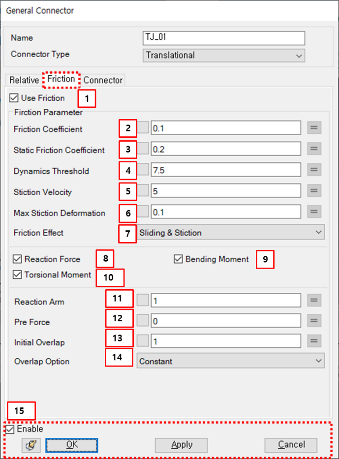
Figure 5.37: Description of Friction parameters in the Translational Joint property dialog
| Parameter | Symbol | Description | Dimension (Range) |
| 1. Use Friction | N/A | If this option is selected, the friction torque will be added to the joint. | N/A |
| 2. Friction Coefficient |  | Use to set the friction coefficient. |
N/A (Real>=0) |
| 3. Static Friction Coefficient |  | Use to set the static friction coefficient. |
N/A (Real>=0) |
| 4. Dynamics Threshold |  | Use to set the dynamic threshold. |
Length/Time (Real>=0) |
| 5. Stiction Velocity |  | Use to set the stiction velocity. |
Length/Time (Real>=0) |
| 6. Max Stiction Deformation |  | Use to set the maximum deformation under stiction. |
Length (Real>=0) |
| 7. Friction Effect | N/A | Use to select one of the friction effects. When is selected, the friction coefficient is calculated from Equation 5–42 ~ Equation 5–47 in the Motion Theory Reference. When is selected, the friction coefficient is calculated from Equation 5–44. When is selected, the friction coefficient is calculated from Equation 5–47. | N/A |
| 8. Reaction Force | N/A | If this option is selected, the reaction forces on x-y plane are considered for the friction torque. | N/A |
| 9. Bending Moment | N/A | If this option is selected, the bending moment is considered for the friction force. | N/A |
| 10. Torsional Moment | N/A | If this option is selected, the torsional moment is considered for the friction torque. | N/A |
| 11. Reaction Arm |  | Use to define the equivalent contact radius |
Length (Real>0) |
| 12. pre force |  | Use to define the pre-defined frictional force | Force |
| 13. Initial overlap |  | Use to define the initial overlap. |
Length (Real>0) |
| 14. Overlap option | N/A | Use to select one of the overlap options. When is selected, the overlap length will be constant as the initial overlap. When is selected, the overlap length is calculated from Equation 5–52 in the Motion Theory Reference. When is selected, the overlap length is calculated from Equation 5–54. | N/A |
| 15. Control buttons | N/A | If all necessary parameters are set, these buttons are enabled. For more information about the control buttons, refer to Entity Properties Access and Modification. | N/A |
Parameters for clearance are defined as shown in the figure and table below. For more information about their usage, you can refer to Clearance in a Translational Joint in the Motion Theory Reference.
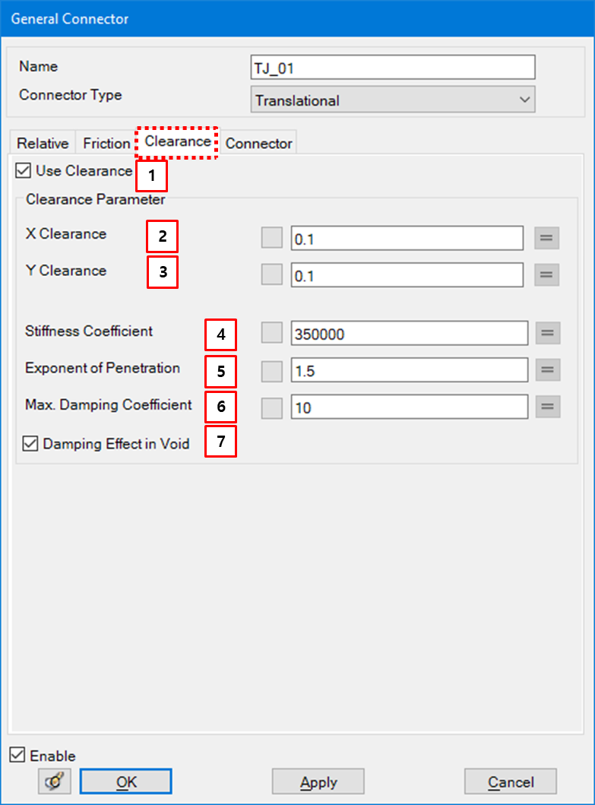
Figure 5.39: Description of Clearance parameters in the Translational Joint property dialog
| Parameter | Symbol | Description | Dimension (Range) |
| 1. Use Clearance | N/A | If this option is selected, clerance will be activated. | N/A |
| 2. X Clearance |  | Use to define the clearance in the x-axis direction of the base marker. |
Length (Real≥0.0) |
| 3. Y Clearance |  | Use to define the clearance in the y-axis direction of the base marker. |
Length (Real≥0.0) |
| 4. Stiffness Coefficient |  | Use to define the contact stiffness. |
Force/Length (Real>0.0) |
| 5. Exponent of Penetration |  | Use to define the exponent of penetration. | N/A |
| 6. Max Damping Coefficient |  | Use to define the maximum damping coefficient. | Force*Time/ Length (Real>0.0) |
| 7. Damping Effect in Void | N/A | Use to activate the damping effect in the vacant space. | N/A |
Advance tab parameters are defined as shown in the figure and table below. For more information on their usage, refer to Restriction Force in a Translational Joint in the Motion Theory Reference.
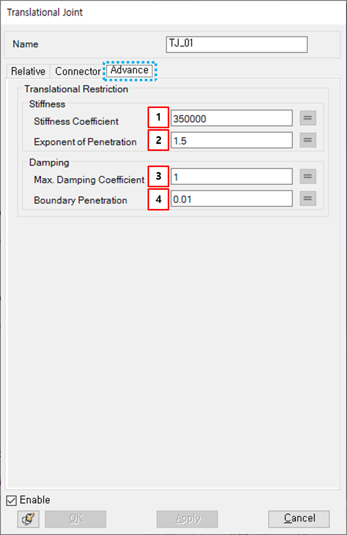
Figure 5.41: Description of Advance parameters in the Translational Joint property dialog
| Parameter | Symbol | Description | Dimension (Range) |
| 1. Stiffness Coefficient |  | Use to set the stiffness coefficient in Restriction Force in a Translational Joint |
Force /(Length^n) (Real≥0.0) |
| 2. Exponent of Penetration |  | Use to set the exponent of penetration in Restriction Force in a Translational Joint |
N/A (Real≥0.0) |
| 3. Max. Damping Coefficient |  | Use to set the maximum damping coefficient in Restriction Force in a Translational Joint |
Force *Time/Length (Real≥0.0) |
| 4. Boundary Penetration |  | Use to set the boundary penetration value in Restriction Force in a Translational Joint |
Length (Real≥0.0) |