


As shown in the figure below, properties such as Name, Sensor Type, Function Name, Sign and so on can be defined in the Simulation Scenario sub-entity window. General Sub-Entity Properties have been introduced in Figure 8.18: General properties of sub-entity pages and toolbar and the special properties are defined in the table below.
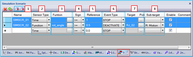
Figure 8.75: Simulation Scenario properties
| Parameter | Symbol | Description | Dimension (Range) |
| 1. Name | N/A | Scenario name. | N/A |
| 2. Sensor Type |
 |
Use to set the sensor type to or . This is one of the variables and is compared with the reference value in the Reference field (below). When is selected, the variable can be defined as follows.

When is selected, the variable can be defined as follows.

| N/A |
| 3. Function |
 | Use to set the function using the Function Expression picker. This option is only available when the sensor type is set to . This grid shows the name of selected Function Expression. | N/A |
| 4. Sign |
 |
Use to define a conditional sentence for the sensor and reference value. Five sentences are supported as follows.
| N/A |
| 5. Reference |
 | Use to set the reference value. |
N/A (Real) |
| 6. Event Type | N/A | Use to set the event type as shown in the Events in a Simulation Scenario table. | N/A |
| 7. Target | N/A | Use to define a target value or entity to which an event is applied as shown in the Events in a Simulation Scenario table. The target entity is only available for and events. | N/A |
| 8. Sub-target | N/A | Use to define a sub-entity of the target entity. This option is needed to control motion of Revolute, Translational and Cylindrical joints. This field has three options for , and . When the option is selected, the target entity is controlled by the event. When or is selected, the rotational motion or translational motion of the target entity is controlled by the event, respectively. | N/A |
The conditional sentence of the simulation scenario can be defined as follows.
 | (8–1) |
Once the Equation 8–69 is satisfied for the first time, the Motion solver generates the event.
Remarks
The name of the ICF file does not support local character sets, or blank and special characters such as /, *, and +.
The event must be triggered at initiation time.
The reporting time duration from the event is determined by the following rule.
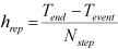
(8–2)
where
 ,
,  and
and  are the simulation end time, event time and
user defined target value or the event, respectively.
are the simulation end time, event time and
user defined target value or the event, respectively.The reporting time duration of the PLT file from the event is determined by the following rule.
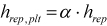
(8–3)
where
 and
and
 are the reporting time
duration and user defined target value for the event, respectively.
are the reporting time
duration and user defined target value for the event, respectively.When an event conflicts with another event, the Motion solver adopts the action of the last defined event.
When a joint or motion is activated, the Motion solver can fail when the constraint equations of the joint are severely violated.
For the event, an inequality condition must be used. If a joint is initially deactivated by a condition, the joint cannot be activated because the constraint equations of the joint can be a redundant constraint. When the reference value is zero and the function is used as a sensor, the reference value is better changed to a non-zero value, such as
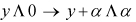 .
.