


Relative motion and connector parameters can be modified from the Cylindrical Joint property dialog. The T-Relative and R-Relative tabs are exactly same as those of a Translational Joint and Revolute Joint, respectively.
Parameters for T-Friction are defined as shown in the figure and table below.
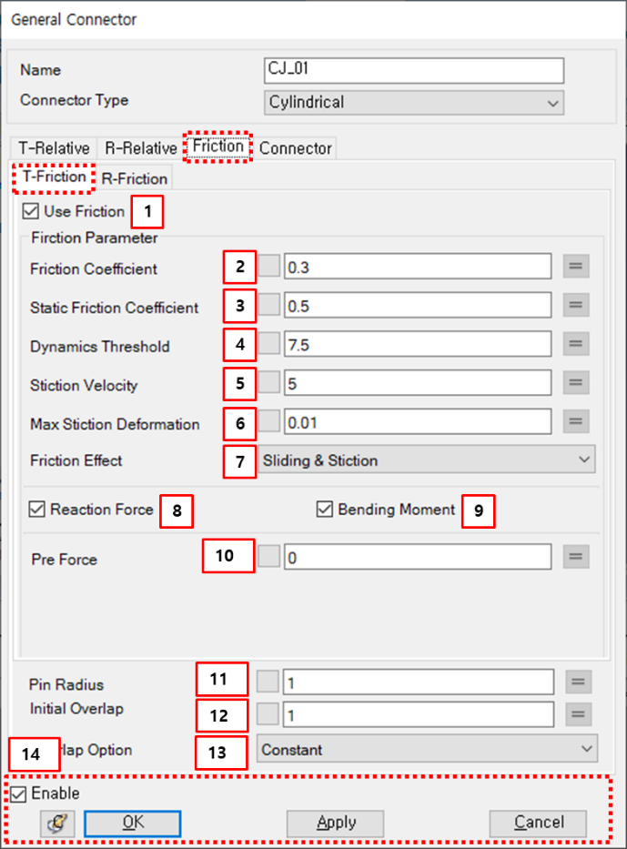
Figure 5.49: Description of T-friction parameters in the Cylindrical Joint property dialog
| Parameter | Symbol | Description | Dimension (Range) |
| 1. Use Friction | N/A | If this option is selected, the friction torque will add to the joint. | N/A |
| 2. Friction Coefficient |  | Use to set the friction coefficient. |
N/A (Real>=0) |
| 3. Static Friction Coefficient |  | Use to set the static friction coefficient. |
N/A (Real>=0) |
| 4. Dynamics Threshold |  | Use to set the dynamics threshold. |
Length/Time (Real>=0) |
| 5. Stiction Velocity |  | Use to set the stiction velocity. |
Length/Time (Real>=0) |
| 6. Max Stiction Deformation |

| Use to set the maximum deformation under stiction. |
Length (Real>=0) |
| 7. Friction Effect | N/A | Use to select one of the friction effects. When is selected, the friction coefficient is calculated from Equation 5–42 ~ Equation 5–47 in the Motion Theory Reference. When is selected, the friction coefficient is calculated from Equation 5–44. When is selected, the friction coefficient is calculated from Equation 5–47. | N/A |
| 8. Reaction Force | N/A | If this option is selected, the radial force is considered for the friction force. | N/A |
| 9. Bending Moment | N/A | If this option is selected, the bending moment is considered for the friction force. | N/A |
| 10. Pre Force |  | Use to set the pre-defined frictional force. | Force |
| 11. Pin Radius |

| Use to define pin radius. |
Length (Real>0) |
| 12. Initial overlap |  | Use to define initial overlap. |
Length (Real>0) |
| 13. Overlap Option | N/A | Use to select one of the overlap options. When " is selected, the overlap length will be constant as the initial overlap. When is selected, the overlap length is calculated from Equation 5–52 in the Motion Theory Reference When is selected, the overlap length is calculated from Equation 5–54 | N/A |
| 14. Control buttons | N/A | If all necessary parameters are set, these buttons are enabled. For more information about the control buttons, refer to Entity Properties Access and Modification. | N/A |
Parameters for R-Friction are defined as shown in the figure and table below.
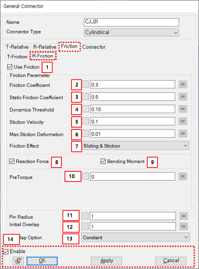
Figure 5.51: Description of R-friction parameters in the Cylindrical Joint property dialog
| Parameter | Symbol | Description | Dimension (Range) |
| 1. Use Friction | N/A | If this option is selected, the friction torque will be added to the joint. | N/A |
| 2. Friction Coefficient |  | Use to set the friction coefficient. |
N/A (Real>=0) |
| 3. Static Friction Coefficient |  | Use to set the static friction coefficient. |
N/A (Real>=0) |
| 4. Dynamics Threshold |  | Use to set the dynamics threshold. |
Length/Time (Real>=0) |
| 5. Stiction Velocity |  | Use to set the stiction velocity. |
Length/Time (Real>=0) |
| 6. Max Stiction Deformation |

| Use to set the maximum deformation under stiction. |
Length (Real>=0) |
| 7. Friction Effect | N/A | Use to select one of the friction effects. When is selected, the friction coefficient is calculated from Equation 5–42 ~ Equation 5–47 in the Motion Theory Reference. When is selected, the friction coefficient is calculated from Equation 5–44. When is selected, the friction coefficient is calculated from Equation 5–47. | N/A |
| 8. Reaction Force | N/A | If this option is selected, the radial force is considered for the friction torque. | N/A |
| 9. Bending Moment | N/A | If this option is selected, the bending moment is considered for the friction torque. | N/A |
| 10. Pre Torque |  | Use to set the pre-defined frictional torque. | Force |
| 11. Pin Radius |

| Use to define pin radius. |
Length (Real>0) |
| 12. Initial overlap |  | Use to define initial overlap. |
Length (Real>0) |
| 13. Overlap option | N/A | Use to select one of overlap option. When is selected, the overlap length will be constant as the initial overlap. When is selected, the overlap length is calculated from Equation 5–52 in the Motion Theory Reference. When is selected, the overlap length is calculated from Equation 5–54. | N/A |
| 14. Control buttons | N/A | If all necessary parameters are set, these buttons are enabled. For more information about the control buttons, refer to Entity Properties Access and Modification. | N/A |
Connector parameters can be found in Constraint Entity Connectors.