


A Beam FE Body generates a finite element with beam and solid4 elements. A solid4 element is not considered for stiffness but it is used for contact geometry. To create a Beam FE Body for contact, the points at both ends of the beam must be selected, and the Y direction, radius, and number of nodes must be entered. This operation is described in the figure and table below.
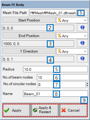
Figure 3.121: Description of parameters in the Beam FE Body dialog
| Parameter | Description |
| 1. Mesh File Path | Use to set the file name and path to create the mesh file. |
| 2. Start Position | Use to set Start Position of the Beam |
| 3. End Position | Use to set End Position of the Beam |
| 4. Y Direction | Use to set the direction vector which determines the reference frame of the beam element with Equation 3–23 ~ Equation 3–27 (for a Beam Element). |
| 5. Radius | Use to set the radius of the section. |
| 6. No. of beam nodes | Use to set number of beam nodes in the longitudinal direction. |
| 7. No. of circular nodes | Use to set number of circular nodes in the section. |
| 8. Name | Use to set name of the created Beam. |
| 9. Control buttons | If all necessary parameters are set, these buttons are enabled. For more information about the control buttons, refer to Entity Creation. |