


User can select a profile formulation for an internal gear set. The cycloid type is supported for internal gear set only.
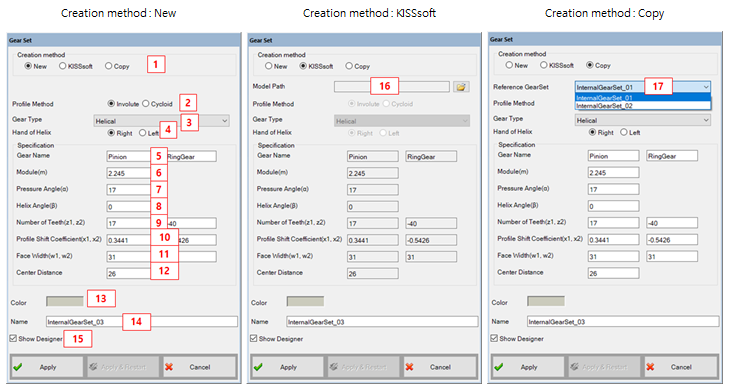
Figure 14.110: Parameters in the creation dialog for involute type internal gear set
| Parameter | Description |
Dimension (Range) |
| 1. Creation Method | Use to set the creation type. When the "Copy" option is selected, the parameters of created gear set can be defined from the parameters of pre-defined gear set. | N/A |
| 2. Profile Method |
Select a profile type. - Involute - Cycloid | N/A |
| 3. Gear Type | Use to select the type of gear. When the "Helical" type is selected, the helix angle and the hand of helix can be activated. | N/A |
| 4. Hand of Helix | Use to select the hand of helix. This parameter is available on the helical type. | N/A |
| 5. Gear Name | Use to set the names of gears. | N/A |
| 6. Module(m) | Use to set the normal module. | N/A |
| 7. Pressure Angle(α) | Use to set the normal pressure angle. |
Degree (Real) |
| 8. Helix Angle(β) | Use to set the helix angle. |
Degree (Real) |
| 9. Number of Teeth(z1,z2) | Use to set the number of tooth for each gear. If the gear type is the internal gear, the value must be negative. |
N/A (Integer≠0) |
| 10. Profile Shift Coefficient (x1,x2) | Use to set the profile shift coefficient. |
Length (Real) |
| 11. Face Width (w1, w2) | Use to set the face width. |
Length (Real>0) |
| 12. Center distance | Use to set the center distance between each gear. This parameter is used only for 2D graphics in designer. |
Length (Real>0) |
| 13. Color | Use to set the color. | N/A |
| 14. Name | Use to set the name of gear set. | N/A |
| 15. Show designer | Use to open the designer automatically. | N/A |
| 16. Model path | Select KISSsoft model file. | N/A |
| 17. Reference Gear set | Select the gear set that has already been created. | N/A |
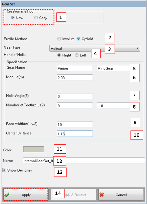
Figure 14.112: Parameters in the creation dialog for a cycloid type internal gear set
| Parameter | Description |
Dimension (Range) |
| 1. Creation Method | Use to set the creation type. When the "Copy" option is selected, the parameters of created gear set can be defined from the parameters of pre-defined gear set. | N/A |
| 2. Profile Method |
Select a profile type. - Involute - Cycloid | N/A |
| 3. Gear Type | Use to select the type of gear. When the "Helical" type is selected, the helix angle and the hand of helix can be activated. | N/A |
| 4. Hand of Helix | Use to select the hand of helix. This parameter is available on the helical type. | N/A |
| 5. Gear Name | Use to set the names of gears. | N/A |
| 6. Module(m) | Use to set the normal module. | N/A |
| 7. Helix Angle(β) | Use to set the helix angle. |
Degree (Real) |
| 8. Number of Teeth (z1,z2) | Use to set the number of tooth for each gear. If the gear type is the internal gear, the value must be negative. |
N/A (Integer≠0) |
| 9. Face Width (w1, w2) | Use to set the face width. |
Length (Real>0) |
| 10. Center distance | Use to set the center distance between each gear. This parameter is used only for 2D graphics in designer. |
Length (Real>0) |
| 11. Color | Use to set the color. | N/A |
| 12. Name | Use to set the name of gear set. | N/A |
| 13. Show designer | Use to open the designer automatically. | N/A |