


Design Parameter properties are defined in the DOE Simulation dialog as shown in the figure below. When the "DP" option is selected in the Design Variable Properties and Design Point Properties, the specified design variables and design points are displayed in the list of design parameters. The bound of the design parameter is determined as shown in the table below.
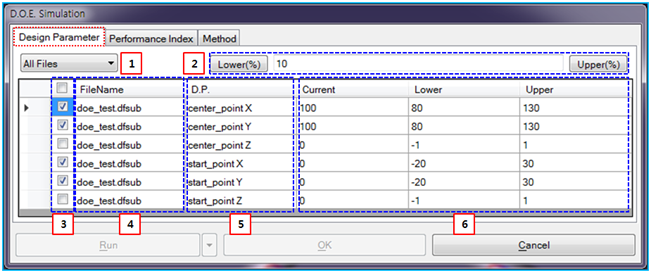
Figure 9.78: Description of Design Parameter properties
| Parameter | Symbol | Description | Dimension (Range) |
| 1. All Files | N/A | Use to set all subsystem files or one specified subsystem file. The design parameters which belong to the selected subsystem are only displayed in the list of design parameter. When the is selected, all design parameters in the model which may have several child subsystems are lied in the list. | N/A |
| 2. Lower(%) and Upper(%) | N/A |
Use to set the bound of the design parameters from % of current value. The bound value determines the lower and upper values of the specified design parameters as follows.

where, |
N/A (Real>0.0) |
| 3. Check Button | N/A | Use to enable the specific design parameter. When this button is checked, the design parameter is available in the DOE simulation. | N/A |
| 4. File Name | N/A | Use to show the name of subsystem file which the design parameters in the list belong to. | N/A |
| 5. D.P. | N/A | Use to show the name of design variable or design point. | N/A |
| 6. Current, Lower, Upper | N/A | Use to show the current value and set the lower and upper values of the design parameters. |
N/A (Real) |


