Reference geometry defines the shape or form of a surface or a solid. Reference geometry includes planes, axes, coordinate systems, and points.
Given direction by ref-plane and ref-axis, such as surface rotate, extrude and mirror transform.
Given shape's local definition by local coordinate system, such as define a plane by a local coordinate system and two other parameters width and length.
Given a position by a ref-point.
You can use reference geometry in the creation of several kinds of features.
You can create several types of reference points to use as construction objects. You can also create multiple reference points that are a specified distance apart on curves. Click View, RefGeom, Ref Point to toggle the display of reference points.
To create a ref-point: Click Point (Reference Geometry toolbar) or click Geometry, Reference Geometry, Reference Point.
In the dialog, select the type of you want to create the point:
- Parameters
Create a point by coordinates. You can also select a local coordinate system and give the coordinates related to this local coordinate system.
- Cir/Sph/Con....
Create a point using center of circle, ellipse, parabola, hyperbola, sphere, torus, or apex of cone.
- Mass Center
Create a reference point at the gravity center or parameter center of the selected shape.
- Cur/Cur Inter
Create reference points at the intersection of the two selected curves or ref-axes. If the two curves are not intersected with each other, you can evaluate related points using the extrema mode. For example, two circles at the same plane, but far from each other, you can get the farthest and nearest points' pairs in two circles using the extrema mode.
- Cur/Surf Inter
Create reference points at the intersection of the selected curve and surface. You can select edge, reference axis, face and reference plane.
- To Cur/Surf
Create reference points by picking positions on edge or face.
- 3 Points Arc
Create a reference point which locates at the center of the circle which created by selected 3 points. You can select vertex, reference point, node, or pick position on edge or face.
- Sample Curve
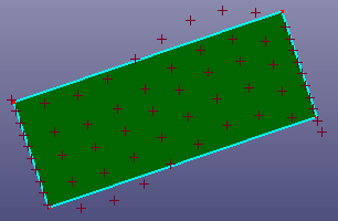
Sample points from curve by methods: Uniform, Curvature and Control Points. Uniform: sample the curve uniformly by distance. Curvature: sample the curve curvaturally. Control Points: if the selected curve is B-spline curve, the sample points are the control points of the B-spline curve. If the curve is not a B-spline curve, the software creates a B-spline curve internally.
- Sample Surf
Sample points from surface by methods: Uniform, Curvature and Control Points. Uniform: sample the surface uniformly in U and V direction. Curvature: sample the surface curvaturally. Control Points: if the selected surface is a B-spline surface, the sample points are the control points of the B-spline surface. If it is not a B-spline surface, the software creates a B-spline surface internally.
- Points Avg
Create a point which locate at the barycenter of the selected points.
- Middle Points
Create middle points between two selected points.
You can create a reference axis, also called a construction axis. Click View, RefGeom, Ref Axis to toggle the display of reference axes.
To create a reference axis: Click Axis(Reference Geometry toolbar) or click Geometry, Reference Geometry, Reference Axis.
In the dialog, select the type of axis you want to create and the items to create the axis:
- Parameters
Create an axis through a point and a direction vector by parameters.
- Line
Create an axis through a line or linear edge.
- Planes Inter
Create axes by the selected planes' intersection.
- Two Pnts
Create an axis by two points.
- Axis of Revol
Create an axis which is the axis of circle/ellipse/cylinder/cone/revolve surface.
- Tan/Nor to Cur
Project the selected point to the selected curve. The result ref-axis will pass the projected point and the direction is the tangent direction on the curve. If the curve and the point locate at the same plane, you can also check "Normal to Curve" to create an axis normal to the curve using the point as reference.
- Point to Plane
Select a plane and a point, the axis will pass the point and normal to the plane.
- Normal to Surf
Select a surface and a point. Project the selected point to the surface. The axis will pass the projected position and normal to the surface.
- Point to Plane
Select a plane and a point, the axis will pass the point and normal to the plane.
- Two Lines
Create an axis normal to the two selected lines and pass the intersection point of the two lines. Checking "Middle" will make the axis locate at the same plane with two selected lines and equal angle with two lines.
You can use planes to sketch, to create a section view of a model, for a neutral plane in a draft feature, and so on. Click View, RefGeom, Ref Plane to toggle the display of reference planes.
To create a construction plane: Click Plane(Reference Geometry toolbar) or click Geometry, Reference Geometry, Reference Plane.
In the dialog, select the type of plane you want to create and the items to create the plane:
- Parameters
Create a plane by an origin point and a normal vector. You can also sketch ref-planes when "Sketch" is checked.
- Throu Line/Pnt
Creates a reference plane passing the selected point and the selected line.
- Normal/Pnt
Creates a reference plane which passes the selected point and normals to the selected line.
- Parallel Pnt/Plane
Create a plane passing through a point and parallel to a plane.
Select a point (the yellow ref-point) and a plane (the highlight front plane) to create a parallel plane.
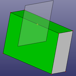
- Rotate Plane
Create a new plane by rotating an existed plane with a selected axis.
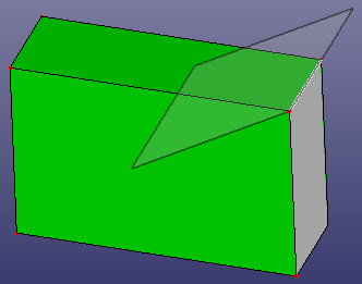
Select a line (the top-right edge of the box) and a plane (the highlight front plane) to create a rotation plane.
- Offset Plane
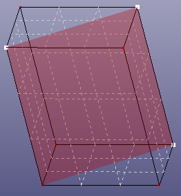
Create several planes parallel to a selected plane, and offset by a specified distance.
Select a plane to offset 5 planes.
- Normal to Cur
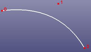
Create a plane through a point and perpendicular to a curve.
Ref-plane normal to the curve at the end point.
- Tangent Surf
Create a plane on a non-planar face or angular surface.
Select the ref-point and the surface to create tangent ref-plane.
- 3 Points
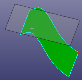
Create a plane passing through 3 selected points.
Plane by 3 Points
- 2 Points
Create a plane normal to a virtual line segment built by 2 points.
- Equation
Create a plane by equation. You can also define any point which the plane should pass through.
- Through 2 Lines
Create a plane passing through two lines. If the two selected lines are not located at the same plane, the first line will be selected as the reference.
You can define a coordinate system for a part. Use this coordinate system with the Surface and Solid modeling tools. Click View, RefGeom, Ref Coordinate System to toggle the display of reference coordinate systems.
To create a coordinate system: Click Coordinate(Reference Geometry toolbar) or click Geometry, Reference Geometry, Reference Coordinate System .
In the dialog, select the type of you want to create the coordinate system:
- Parameters
Create a coordinate system through an origin point, a Z-axis and a X-axis parameters.
- Origin/Dir
Create a coordinate system by selecting an origin point, a Z-axis line, and a X-axis line. By default, you can select only an origin point and Z-axis line, the X-axis line will be calculated by Z-axis.
- In Cur/Surf
Create a coordinate system by select a point on the selected curve or the selected surface. The selected point is firstly projected to the curve or surface. For the curve, the projected point will be treated as the origin, the tangent vector of the project position on the curve will be treated as the Z-direction. And the X-axis is chosen randomly. For the surface, the projected point will be treated as the origin, the X-axis and the Y-axis are the U and V tangent vectors of the project position on the surface.
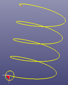
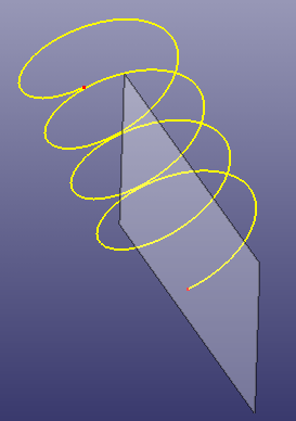
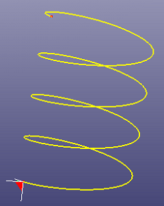
Figure 5.5: Select the vertex from the helix, using In Cur/Surf method to create a local coordinate system
- 3 Points
Create a coordinate system by 3 points. You can choose type as XOY, YOZ, or ZOX.
- Sample Cur
Create a series of coordinate systems in the selected curve.
- Sample Surf
Create a series of coordinate systems in the selected surface.
- Principal Axes
Using principal component analysis (PCA) method to calculate a principal axes coordinate system by the selected entities.
- Euler Angles
The Euler angles are three angles that describe the orientation of a rigid body with respect to a fixed coordinate system. They can also represent the orientation of a mobile frame of reference in physics or the orientation of a general basis in 3-dimensional linear algebra.
There are six possibilities of choosing the rotation axes for Proper Euler Angles. In all of them, the first and third rotation axes are the same. The six possible sequences are:
z-x’-z″ x-y’-x″ y-z’-y″ z-y’-z″ x-z’-x″ y-x’-y There are six possibilities of choosing the rotation axes for Tait–Bryan Angles. The six possible sequences are:
x-y’-z″ y-z’-x″ z-x’-y″ x-z’-y″ z-y’-x″ y-x’-z″