


- Shape Mesh
Simple shell/solid meshing interface.
- Auto Mesh
Surface mesh interface.
- Solid Mesh
Solid mesh interface.
- Block Mesh
2/3 D block mesher interface.
- N-Line Mesh
2, 3, and 4 line mesh interface.
- 2D Mesh
2D mesh sketchboard interface.
- Tetrahedron Mesh
Tetrahedron mesher interface.
- Blank Mesh
Blank mesher interface.
- Bulk Fluid
Bulk fluid pipe meshing interface.
- Element Generation
Create beam, shell, and solid elements.
- Node Edit
Show, create, delete, and modify nodes.
- Element Edit
Show, create, delete, and modify elements.
- 2D NURBS
Show, create, delete, and modify 2D FEM NURBS keyword.
- 3D NURBS
Show, create, delete, and modify 3D FEM NURBS keyword.
- Mass Trim
Mass trim interface.
- Spot Welding
Generate spotweld elements from a spotweld file.
- SPH Generation
Sphere particle generation interface.
- Disc Sphere Generation
Disc Sphere generation interface.
- Multi Solver Mesh
Convert between Multiple Solver mesh and mesh.
- Result Mapping
Initial stress mapping interface.
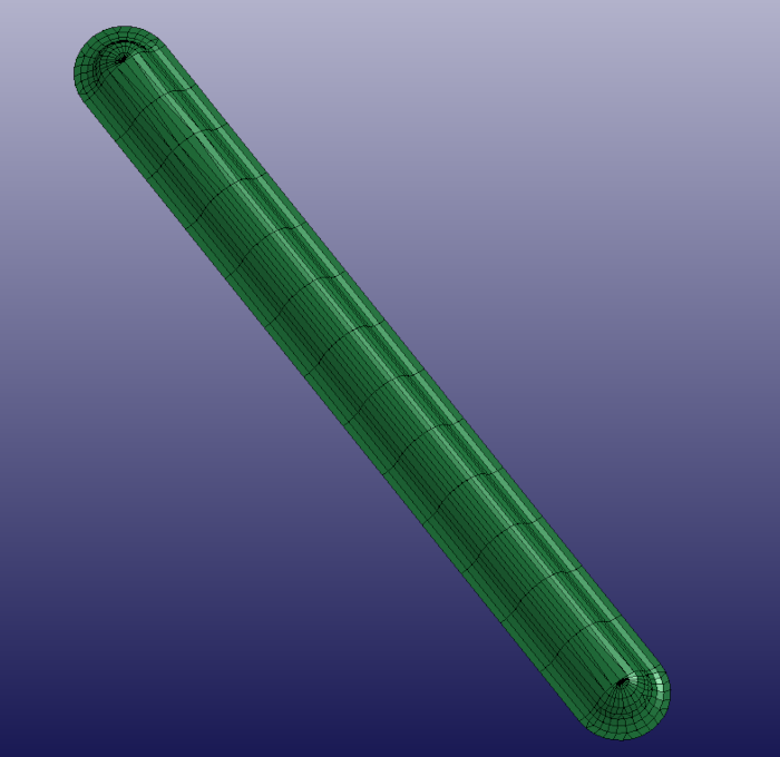
This interface, often used for generating solid meshes for ALE simulations, can be used to generate solid and shell meshes.
- Box Solid
Define a box and generate solid mesh of it.
- Box Shell
Define a box and generate shell mesh of it.
- 4N Shell
Define four node surface and generate shell mesh of it.
- Sphere Solid
Define a sphere and generate solid mesh of it.
- Sphere Shell
Define a sphere and generate shell mesh of it.
- Cylinder_Solid
Define a cylinder and generate solid mesh of it.
- Cylinder_Shell
Define a cylinder and generate shell mesh of it.
- Circle_Shell
Define a circle and generate shell mesh of it.
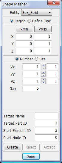
- Region
Use General Selection Interface to get region max and min values.
- Define_Box
Use Entity Operation Interface to get box max and min values.
- PMin/PMax
Use Position Dialog to get minimum/maximum point.
- X/Y/Z
Enter x/y/z-coordinates of minimum and maximum point.
- Number
Enter number of elements along x/y/z.
- Size
Enter size along x/y/z.
- Vx/Vy/Vz
Enter Number/Size along x/y/z.
- Gap
Extend min/max of box by this value.
- Target Name
Enter target part name.
- Target Part ID
Enter target part ID.
- Start Element ID
Enter starting element ID.
- Start Node ID
Enter starting node ID.
- Create
Create mesh for the entity.
- Reject
Reject the created mesh.
- Accept
Accept the created mesh.
- Done
Exit meshing interface.
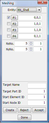
- Checkbox P1/P2/P3/P4
Use General Selection Dialog to Pick node for point 1/2/3/4.
- Button P1/P2/P3/P4
Use Position Dialog to get point 1/2/3/4.
- Text P1/P2/P3/P4
Enter coordinates in format "x, y, z" for point 1/2/3/4.
- NxNo.
Enter number of elements along x.
- NyNo.
Enter number of elements along y.
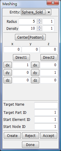
- Radius
Enter radius of sphere.
- Density
Enter density of sphere.
- Center[Position]
Use Position Dialog to get sphere center.
- x/y/z
Enter x, y, z of the sphere center.
- Direct1
Call Direction Dialog to get direction 1.
- Direct2
Call Direction Dialog to get direction 2.
- dx/dy/dz
Set direction x/y/z for 1/-1 (toggles).
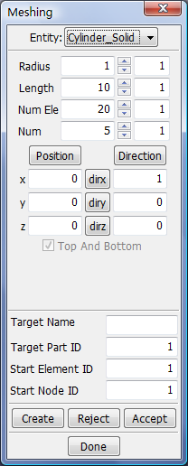
- Radius
Enter cylinder radius.
- Length
Enter cylinder length.
- Num Ele
Enter number of elements in circumferential direction
- Num
Enter number of elements along the length of the cylinder.
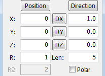
- Position
Call Position Dialog to get position.
- Direction
Call Direction Dialog to get direction.
- dirx/diry/dirz
Set direction x/y/z for 1/-1 (toggles).
- Top And Bottom
Extend min/max of box by this value.
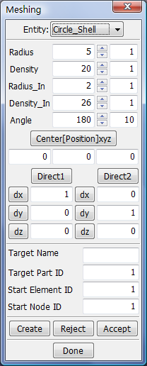
- Radius
Radius of circle.
- Density
Density of Circle (Must more than 2).
- Radius_In
Radius of circle inside.
- Density_In
Density of Circle Inside (Must more than 2).
- Angle
Span Angle.
- Center[Position]xyz
Call Position Dialog to get position.
- Direct1
Call Direction Dialog to get direction 1.
- Direct2
Call Direction Dialog to get direction 2.
- dx/dy/dz
Set direction x/y/z for 1/-1 (toggles).
This interface is for surface mesh generation. Two meshing methods are available: By size and By Deviation.
- Auto Mesh
Size mode creates uniformly sized elements.
- Tool Mesh
Specifically for metalforming applications where surfaces may contain very small radii that need to be meshed accurately, and at the same time have flat areas that require a relatively coarse mesh. Tool meshing requirements are very different from those of structural finite element analysis.
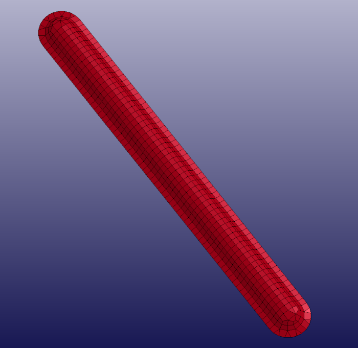
- Two kind mesh comparison
Show the difference between size-based and deviation-based.
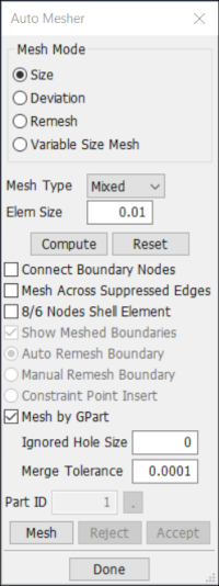
- Size
Select the size mode.
- Deviation
Select the deviation mode.
- Mesh Type
Generate triangle mesh only or mixed.
- Elem Size
Enter average element size.
- Compute
Compute mesh parameter by model extend.
- Reset
Reset mesh parameter to default.
- Show Meshed Boundaries
Before Accept and After Mesh, will become sensitive. Show the boundary node as blank square.
- Auto remesh boundary
Before Accept and After Mesh, will become sensitive. On the boundary, left-click to increase the node num and right-click to decrease it. Then automesh it according to the new boundary.
- Manual remesh boundary
Before Accept and After Mesh, will become sensitive. On the boundary, left-click to add a new node and right-click to remove a node. Then automesh it according to the new boundary.
- Mesh By GPart
The mesh generated from same GPart will be organized into same part.
- Ignored Hole Size
Holes under specified size will be ignored.
- Part ID
Assign new generated mesh to this part or create a new part if this part id doesn't exist.
- Mesh
Generate shell mesh for selected surfaces.
- Reject
Reject the last operation.
- Accept
Accept the last operation.
- Done
Exit this dialog.
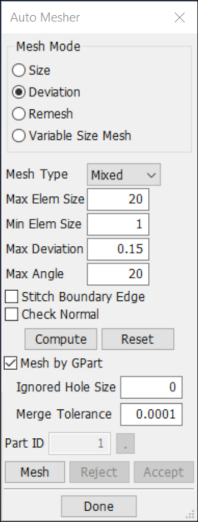
- Max Elem Size
Enter maximum element size.
- Min Elem Size
Enter minimum element size.
- Max Deviation
Enter maximum deviation ratio.
- Max Angle
Enter maximum feature angle.
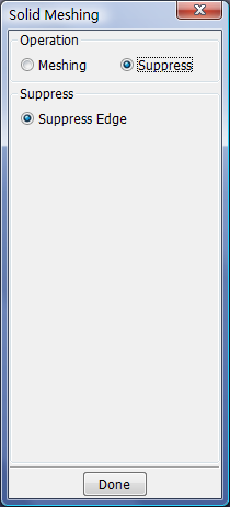
Generate solid mesh of mappable volumes.
- Meshing
Generate solid mesh manually or automatically.
- Suppress
Suppress geometry edges which resist sweeping.
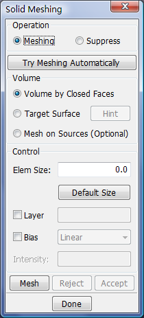
- Try Meshing Automatically
Once the decomposition is done, click this button try to mesh automatically. all the volumes have to be mappable, otherwise unmappable volume will be omitted.
- Volume by Closed Faces
Pick volume to be sweep on graphic area. For manual purpose only.
- Target Surface
Pick face as sweep target on graphic area. For manual purpose only.
- Hint
Click until found the proper target face.
- Mesh on Sources(Optional)
Pick sources' mesh if needed. For manual purpose only.
- Elem Size
Specify the element size.
- Default Size
Click to get the reference element size.
- Layer
Check to enable layer control. For manual purpose only.
- Bias
Check to enable bias control. For manual purpose only.
- Intensity
Specify the bias intensity. For manual purpose only.
- Mesh
Generate solid mesh. For manual purpose only.
- Reject
Reject the last sweep.
- Accept
Accept all sweep.
- Done
Exit the interface and accept all sweep.
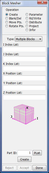
This interface is for index based mesh generation and is similar to mesh generation methods used in LS-INGRID. This capability is under development and eventually will be expanded to be a very powerful addition to LS-PrePost.
- Create
Create blocks.
- Parameter
Parameter and Expression.
- Blank/Del
Blank or delete blocks.
- Rd/Write
Read and write command files.
- Move Pts
Move points.
- Distribute
Distribute blocks' nodes.
- Rotate Pts
Rotate points.
- Project
Project points/lines/surfaces of blocks to geoemtry.
- Info
Show internal node coordinate of given block.
- Multiple Blocks
Create multi blocks.
- Single Block
Create single blocks.
- Butterfly Block
Create a butterfly block.
- Create
Create blocks.
- Parameter
Parameter and Expression.
- Bland/Del
Blank or delete blocks.
- Rd/Write
Read and write command files.
- Move Pts.
Move points.
- Distribute
Distribute blocks' nodes.
- Rotate Pts
Rotate points.
- Project
Project points/lines/surfaces of blocks to geoemtry.
- Info
TODO
- Type
Select block type.
- I Index List
I index list for blocks.
- J Index List
J index list for blocks.
- K Index List
K index list for blocks.
- X Position List
X coordinate for blocks
- Y Position List
Y coordinate for blocks.
- Z Position List
Z coordinate for blocks.
- Part ID
The generated mesh will belong to.
- Create
Create the block.
- Reject
Reject the last operation.
- Accept
Accept the last operation.
- Done
Exit interface.
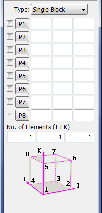
- P1
When check box is checked, pick from graphic. Click button P1 to call Position Dialog to create a Point, or enter x/y/z.
- Px
Same as P1
- No. of Elements(I J K)
Enter number of elements along I, J, K.
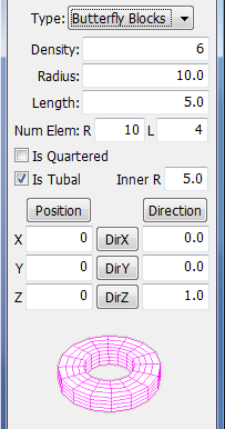
- Density
Density of the cylinder perimeter.
- Radius
Radius of the cylinder.
- Length
Length of the cylinder.
- R
Number of elements in Radius direction.
- L
Number of elements in Length direction.
- Is Quartered
- Is Tubal
The cylinder is empty.
- Inner R
Sensitive when Is Tubal is checked. The inner raidus of cylinder.
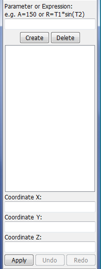
- Parameter or Expression
Enter parameter or expression. Such as A=150 or R=T1*sin(T2).
- Create
Create a parameter or expression.
- Delete
Delete a parameter or expression.
- Coordinate X
Function to evaluate x coordinate.
- Coordinate Y
Function to evaluate y coordinate.
- Coordinate Z
Function to evaluate z coordinate.
- Apply
Apply eval function to current domain block.
- Undo
Undo the last operation.
- Redo
Redo the last Undoed operation.
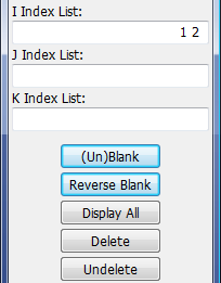
- I Index List
I coordinate of blocks to be blank or delete.
- J Index List
J coordinate of blocks to be blank or delete.
- K Index List
K coordinate of blocks to be blank or delete.
- (Un)Blank
Blank blocks.
- Reverse Blank
Reverse blank status of blocks.
- Display All
Display all blocks.
- Delete
Delete blocks.
- Undelete
Undelete blocks.
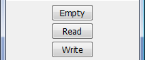
- Empty
Empty current buffer for blockm commmand.
- Read
Read command file.
- Write
Write command file.
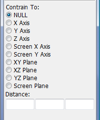
- NULL
No constraint.
- X Aixs
Constraint to X Axis.
- Y Aixs
Constraint to Y Axis.
- Z Aixs
Constraint to Z Axis.
- Screen X Axis
Constraint to screen X Axis.
- Screen Y Axis
Constraint to screen Y Axis.
- XY Plane
Constarint to XY Plane.
- XZ Plane
Constarint to XZ Plane
- YZ Plane
Constarint to YZ Plane.
- Screen Plane
Constraint to screen plane.
- Distance
Sensitive according to former option. the distance on x/y/z direction.
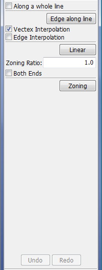
- Along a whole line
Distribute edge along a whole line.
- Edge along line
Distribute edge along line.
- Vectex Interpolation
Vectex Interpolation in Bi-linear and Tri-linear Multiple Faces and Solids Interpolation.
- Edge Interpolation
Edge Interpolation in Bi-linear and Tri-linear Multiple Faces and Solids Interpolation.
- Linear
Apply Linear Interpolation.
- Zoning Ratio
Zoning Ratio (a positive number).
- Both Ends
Relative spacing of nodes of an edge from both ends.
- Zoning
Apply Edge Zoning.
- Undo
Undo last interpolation.
- Redo
Redo last interpolation.
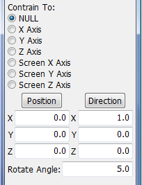
- NULL
No constraint.
- X Aixs
Constraint to X Axis.
- Y Aixs
Constraint to Y Axis.
- Z Aixs
Constraint to Z Axis.
- Screen X Axis
Constraint to screen X Axis.
- Screen Y Axis
Constraint to screen Y Axis.
- Screen Z Axis
Constraint to screen Z Axis.
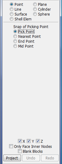
- Project to point.
Project to point.
- Line
Project to line.
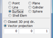
- Surface
Project to surface.
- Shell Element
Project to shell elements.
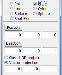
- Plane
Define a plane with an origin and a vector.
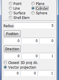
- Cylinder
Define a Cylinder with an origin, a vector and a radius.
- Sphere
Define a Sphere with an origin and a radius.
- Point
Project to point.
- Line
Project to line.
- Surface
Project to surface.
- Shell Element
Project to shell elements.
- Plane
Project to a plane.
- Cylinder
Project to cylinder.
- Sphere
Project to sphere.
- Pick Point
Get XYZ at pick location on curve.
- Nearest Point
Get XYZ at nearest point on curve.
- End Point
Get XYZ at end of curve.
- Mid Point
Get XYZ at middle of curve.
- X
Project in X Component.
- Y
Project in Y Component.
- Z
Project in Z Component.
- Only Face Inner Nodes
Project the Inner nodes when projecting Face(s).
- Blank Blocks
Blank or unblank Blocks.
- Project
Project the Block.
- Undo
Undo last Projection.
- Redo
Redo last Projection.
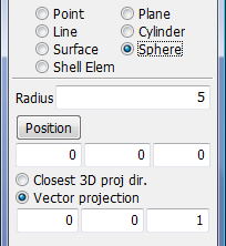
- Closest 3D proj dir.
Project Block to mesh in closet 3D direction.
- Vector projection
Project Block in specified vector direction.
- Position
Select a Coordinate as the Orginal Point.
- Direction
Select a Direction as Plane Normal.
- Radius
Enter the radius for cylinder.
- Position
Select a Coordinate as the Orginal Point.
- Direction
Select a Direction as Plane Normal.
- Closest 3D proj dir.
Project Block to mesh in closet 3D direction.
- Vector projection
Project Block in specified vector direction.
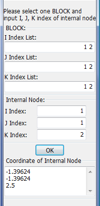
- I Index List
I Coordinate of one block.
- J Index List
J Coordinate of one block.
- K Index List
K Coordinate of one block.
- I Index
I Coordinate of one Internal Node.
- J Index
J Coordinate of one Internal Node.
- K Index
K Coordinate of one Internal Node.
- OK
Get the internal node coordinate.
- Coordinate of Internal Node
Show internal node coordinate in the list.
This interface is for shell mesh generation using curves and often useful in cases where a topology mesher leaves holes due to missing CAD surface data.
- 2 Line Shell
Create a mesh between 2 lines
- line sweep
Create a mesh by sweeping one line along another line
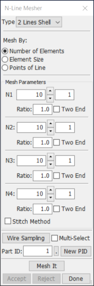
- Number of elements
Mesh by number of elements.
- Element size
Mesh by element size.
- Point of Line
Mesh by existing points of line.
- N1
Enter or adjust number of elements along line 1.
- Ratio
Bias radio.
- Two End
Bias from two end.
- N2
Enter or adjust number of elements along line 2.
- N3
Enter or adjust number of elements along line 3.
- N4
Enter or adjust number of elements along line 4.
- Part Id
Enter or select target part ID.
- New PID
Get new default part ID.
- Mesh It
Perform meshing.
- Accept
Accept the created mesh.
- Reject
Reject the created mesh or the selected lines.
- Done
Exit the nLMesh Interface.
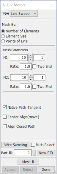
- N1
Enter or adjust number of elements along cross section.
- Ratio
Bias ratio.
- Two End
Bias from two end.
- N2
Enter or adjust number of elements along sweep path.
- Native Path Tangent
Use native curve tangent as sweep direction.
- Center Align(move)
Generate the shell mesh with the sweep path center aligned.
This interface is for 2D mesh generation. Firstly, user should create some points, lines, circles or circular arc in sketch board. And use filleting, extending, trimming, deleting and transforming tools to modify curves. Finally, using those curves and mesh tools to generate 2D mesh. You can also create 3d cone and sphere mesh directly in this dialog.
Use this interface to generate a solid mesh of tetrahedron elements.
- Skin Remesh
Remesh a skin surface.
- Tetrahedral Mesh
Generate a tetrahedral mesh of a skin surface.
- Move
Move skin mesh or tetrahedral mesh to a new position.
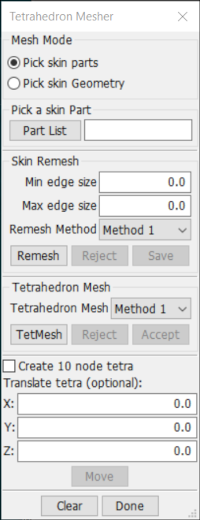
- Pick a skin Part
pick a part from graphic when entering this dialog.
- Part List
Popup list of current parts for selection.
- Min edge size
Enter or change minimum element edge size for remesher.
- Max edge size
Enter or change maximum element edge size for remesher.
- Remesh
Remesh the skin surface.
- Reject
Reject the remesh operation.
- Save
Save skin or remesher skin as a new part.
- TetMesh
Prepare selected part and send to tetrahedron mesher.
- Reject
Reject tet mesh.
- Accept
Accept tet mesh.
- Create 10 node tetra
Create 10 node tetra elements instead of 4 node. Only take effect with "Accept".
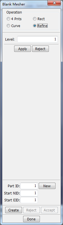
This interface is primarily intended for mesh generation of blanks for metalforming simulations, but it may also have applications in other areas.
- 4 Pnts
Using 4 Corner Nodes (of a blank) and Element Size to generate a mesh.
- Rect
Mesh rectangle of given Length and Width with element size or number of elements.
- Curve
Allows a mesh to be created on an enclosed curve. Element alignment can be along global axis or user defined. Mesh boundary options are as follows: Smoothed, Left Jagged (and optionally filled with trias), or No-Trim (creates a rectangular blank without trimming.
- Refine
Multi-level refine.
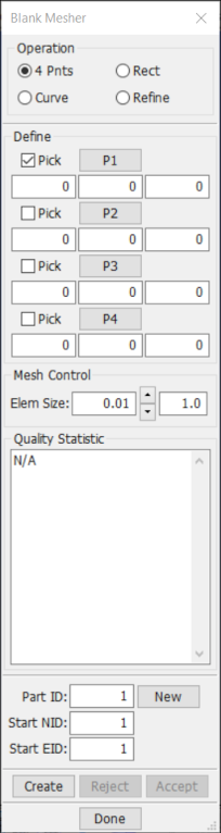
- Pick
Pick node on model to define Node 1/2/3/4.
- P1
Call Position Dialog for Points 1.
- P2
Call Position Dialog for Points 2.
- P3
Call Position Dialog for Points 3.
- P4
Call Position Dialog for Points 4.
- Elem Size
Element size for the blank.
- Quality Statistic
Statistic quality of generated elements before accept.
- Part ID
Part ID for the current blank.
- New
Get a new part ID from the current model.
- Start NID
The starting node id of of new created blank mesh.
- Start EID
The starting element id of of new created blank mesh.
- Create
Create the blank mesh.
- Reject
Reject the last operation.
- Accept
Accept the last operation.
- Done
Exit this dialog.
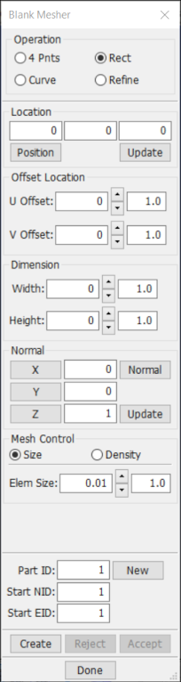
- Location
the left bottom corner of this rectangle.
- Position
Call Position Dialog for location4.
- Update
Update the location.
- U Offset
Enter or adjust plane center in the u direction.
- V Offset
Enter or adjust plane center in the v direction.
- Width
Enter or adjust width of blank.
- Height
Enter or adjust height of blank
- X
Change plane normal to global x.
- Y
Change plane normal to global y.
- Z
Change plane normal to global z.
- Normal
Call Direction Dialog to creat plane normal.
- Update
Update plane normal.
- Size
Give element size for blank.
- Density
Give number of elements for blank.
- Elem Size
Set or adjust element size for the blank (along diagonal).
- U Density
Set or adjust number of elements along u direction.
- V Density
Set or adjust number of elements along v direction.
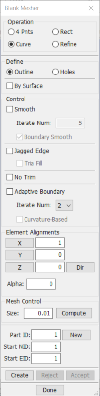
- Outline
Pick curve(s) to define the outline boundary.
- Holes
Pick curve(s) to define holes.
- By Surface
Define outline and holes by surface
- Smooth
Smooth the interior nodes after trimming (enter number of iterations).
- Iterate Num
number of smoothing iterations.
- Boundary Smooth
Smooth the nodes on the boundary after trimming.
- Jagged Edge
Do a rought trim keeping the quadratic shape of the elements.
- Tria Fill
Fill interior boundary notches with triangular elements.
- No Trim
Create a quadratic mesh that covers the curves but performs no trim.
- X
Set alignment direction along X.
- Y
Set alignment direction along Y.
- Z
Set alignment direction along Z.
- Dir
Call Direction Dialog to create alignment for the elements.
- Alpha
Rotate the above given alignment direction by this angle.
- Size
Element size for the blank.
This interface is used for generating bulk fluid pipe mesh.
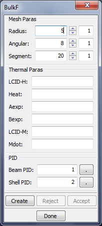
- Radius
Radius of the pipe.
- Angular
Angular of the pipe.
- Segment
Segment of the path.
- LCID-H
Load curve ID for H.
- Heat
Heat transfer coefficient.
- Aexp
A exponent.
- Bexp
B exponent.
- LCID-M
Load curve ID for mass flow rate.
- Mdot
Mass flow rate.
- Beam PID
Enter beam part ID.
- Shell PID
Enter shell part ID.
- Create
Preview the mesh.
- Reject
Reject the created mesh.
- Accept
Accept the created mesh.
- Done
Exit the bulk fluid pipe mesh interface.
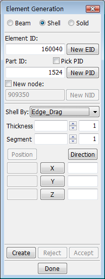
This interface provides a variety of methods for generating beam, shell, and solid elements.
- Beam
Generate beam elements.
- Edge
Create Beam by Edge.
- Curve
Create Beam by Curve.
- Node Drag
Create Beam by Node_Drag.
- Node Spin
Create Beam by Node_Spin.
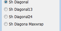
- Shell_Diagonal
Create Beam by Shell_Diagonal.
- Shell
Generate shell elements.
- Solid_Surface, Solid_Face, or Edge_Extend
Create shell by Solid_Surface, Solid_Face or Edge_Extend.
- Edge_Drag
Create shell by Edge_Drag.
- Edge_Spin
Create shell by Edge_Spin.
- Segment_Set
Create shell by Segment_Set.
- Fill_Holes
Create shell by Fill_Holes.
- Cohesive
Create cohesive shell.
- Solid
Generate solid elements.
- Solid_Face_Drag, Solid_Face_Offset or Solid_Face_Spin
Create solid by Solid_Face_Drag, Solid_Face_Offset or Solid_Face_Spin.
- Shell_Drag, Shell_Offset or Shell_Spin
Create solid by Shell_Drag, Shell_Offset or Shell_Spin.
- Shell_Thickness
Create solid by Shell_Thickness.
- Two_Shell_Sets
Create solid by Two_Shell_Sets.
- Shell_Sweep
Create solid by Shell_Sweep.
- Tetra_2_Ten or Hex_2_Tetra
Create solid by Tetra_2_Ten or Hex_2_Tetra.
- Cohesive
Create cohesive solid.
- Sample
- Sample1:
Show how to create element Beam.
- Sample2:
Show how to create element Shell.
- Sample3:
Show how to create element Solid.
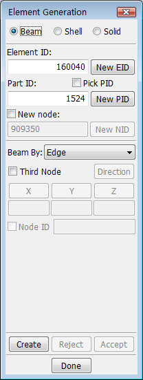
- Element ID
Enter new element starting ID.
- New ID
Use default new element ID.
- Part ID
Enter part ID for newly generated elements.
- Pick PID
Pick part ID from graphics, part type must be consistent with the element type to be created.
- New PID
Use default new part ID.
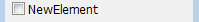
- New node
Check to create new nodes.
- Beam By
Set beam element generation method.
- Create
Create element.
- Reject
Reject last generated element.
- Accept
Accept all new generated elements.
- Done
Exit from element generate interface.
Generate beam elements.
- Third Node
Set third node on/off.
- Direction
Get direction by Direction Dialog.
- X
Set X direction.
- Y
Set Y direction.
- Z
Set Z direction.
- Node ID
ID of the third node.
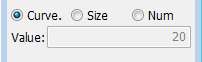
- Curve.
Create beam just be curve without any change.
- Size
Curve mesh by element size.
- Num
Curve mesh by number of element.
- Value
Enter size or number of elements (if zero segment by points).
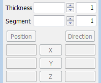
- Thickness
Set total thickness for generation.
- Segment
Set number of segments for generation.
- Direction
Get direction by Direction Dialog.
- X
Set direction 1,0,0 (click 2nd time to reverse).
- Y
Set direction 0,1,0 (click 2nd time to reverse).
- Z
Set direction 0,0,1 (click 2nd time to reverse).
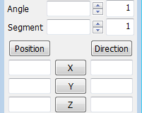
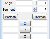
- Angle
Set total angle for generation.
- Segment
Set number of segments for generation.
- Position
Get position with Position Dialog.
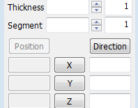
- Thickness
Set total thickness for generation.
- Segment
Set number of segments for generation.
- Direction
Get direction by Direction Dialog.
- X
Set direction 1,0,0 (click 2nd time to reverse).
- Y
Set direction 0,1,0 (click 2nd time to reverse).
- Z
Set direction 0,0,1 (click 2nd time to reverse).
- Angle
Set total angle for generation.
- Segment
Set number of segments for generation.
- Position
Get position with Position Dialog.
- SSegId
Popup set segment id list.
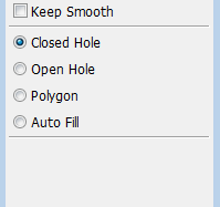
- Keep Smooth
Keep the new element smooth with the neighbors.
- Closed Hole
Pick a node on the edge of hole.
- Open Hole
Pick a node on the edge and a closing line.
- Polygon
Pick nodes to define a polygon to fill.
- Auto Fill
Fill all holes smaller than size specified.
Open Hole Option
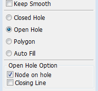
- Node on hole
Pick a node on the hole.
- Closing Line
Pick a closing line.
Auto Fill Option
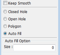
- Size
Hole size.
Cohesive elements are used to model an adhesive connection between elements which may lose its bond. Initially, the cohesive elements have zero volume.
Cohesive shell elements can be created at element edges shared by two shell elements. You must specify a (temporary) beam part which defines the cohesive interface. That is, the shell edges where the cohesive elements will be inserted.
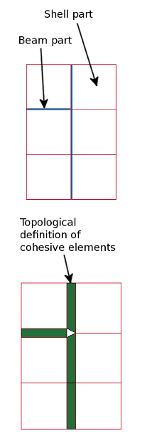
- Shell part
Select the shell part(s) to be connected by cohesive elements.
- Beam part
Select the beam part(s) which defines where cohesive elements will be created.
The image to the left shows a shell part where all elements are connected and the beam part shows where to insert cohesive elements. The image beneath shows the topological connection after the cohesive elements have been created.
The elements in the shell part have been disconnected at locations for the selected beam part. Cohesive shell elements with zero volume have been inserted at these locations.
Create a solid from another type of object.

- Thickness/Angle
Set total thickness or angle for generation.
- Segment
Set number of segments for generation.
- Direction
Get direction by Direction Dialog.
- X
Set direction 1,0,0 (click 2nd time to reverse).
- Y
Set direction 0,1,0 (click 2nd time to reverse).
- Z
Set direction 0,0,1 (click 2nd time to reverse).
- Position
Get position with Position Dialog.
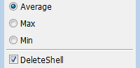
- Average
Set thickness for average.
- Max
Set thickness for max.
- Min
Set thickness for min.
- DeleteShell
Delete shell after create solid.
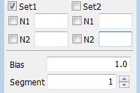
- Set1
Select shell elements for set 1.
- N1
Pick or enter reference node 1 on set 1.
- N2
Pick or enter reference node 2 on set 1.
- Set2
Select shell elements for set 2.
- N1
Pick or enter reference node 1 on set 2.
- N2
Pick or enter reference node 2 on set 2.
- Bias
Set bias value at shell set 1.
- Segment
Set number of segments for generation.
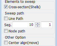
- Cross-section(Shells)
Select shell elements as cross-section.
- Line Path
Select a line as sweep path.
- Seg.
Set num. of segments along the line.
- Node path
Select a node as sweep path.
- Center align(move)
Align selected elements center with the path.
The main purpose of this interface is to create new nodes in various ways, and there are several methods of replacing, aligning, and modifying nodal locations to assist in mesh clean-up.
- Create
Create nodes interface.
- Replace
Replace or merge nodes interface.
- Delete
Delete nodes interface.
- Align
Align nodes interface.
- Modify
Modify nodes interface.
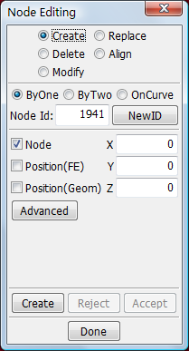
- ByOne
Create one node.
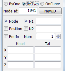
- ByTwo
Creation will include both head and tail nodes.
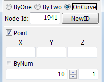
- OnCurve
Create nodes on a curve.
- Node Id
Input node id.
- NewID
Get new default ID.
- Node
Pick node on model to define new node coordinates.
- Position(FE)
Pick a position(FE) to define new node coordinate.
- Position(Geom)
Pick a position(Geom) to define new node coordinate.
- X
Enter X coordinate of new node.
- Y
Enter Y coordinate of new node.
- Z
Enter Z coordinate of new node.
- Advance
Advanced pick position dialog.
- Create
Create nodes and put to temp buffer.
- Reject
Reject last created nodes.
- Accept
Commit created nodes and clear all of them from screen.
- Done
Exit this interface.
- Node
Pick node on model to define new node coordinate.
- Position
Pick a position to define new node coordinate.
- EndIn
Create new nodes at N1 and N2 also.
- N1
Pick node 1 or point to define first point.
- N2
Pick node 2 or point to define second point.
- Num
Set create node number.
- HeadX
Head x coordinate.
- HeadY
Head y coordinate.
- HeadZ
Head z coordinate.
- TailX
Tail x coordinate.
- TailY
Tail y coordinate.
- TailZ
Tail z coordinate.
- Point
Pick a point on a line.
- X
Enter X coordinate of new node.
- Y
Enter Y coordinate of new node.
- Z
Enter Y coordinate of new node.
- ByNum
The number of nodes will create on a line.
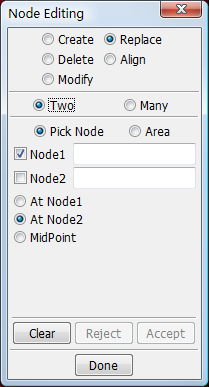
- Two
Replace node by two.
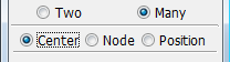
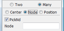
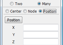
- Many
Replace many nodes.
- Pick Node
Pick node.
- Area
By area select nodes.
- Node1
Pick node on model to define node 1.
- Node2
Pick node on model to define node 2.
- At Node1
Move node2 to node1.
- At Node2
Move node1 to node2.
- MidPoint
Move node1 and node2 to midpoint.
- Clear
Clear node 1 and 2.
- Reject
Reject last replacement node.
- Accept
Accept replacement node.
- Done
Exit this interface.
- Center
Take center for replace target position.
- Node
Pick node for replace target node.
- Position
Call Position Dialog and get target position.
- PickNd
Pick node for replace target position.
- Node
Node id for replace target node.
- Position
Call Position Dialog and get position.
- X
Enter X coordinate of new point 2.
- Y
Enter Y coordinate of new point 2.
- Z
Enter Z coordinate of new point 2.
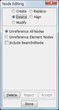
- Unreference All Nodes
Delete Unreference All Nodes.
- Unreference Element Nodes
Delete Unreference Element Nodes.
- Include Beam3rdNode
Ixclude beam third node in selection.
- Delete
Delete selected nodes.
- Reject
Cancel last deletion.
- Accept
Commit deleted node.
- Done
Exit this interface.
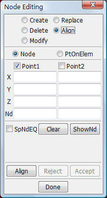
- Node
Define points by node and pick nodes to align.
- PtOnElem
Define points on elements and pick nodes to align.
- Point1
Pick or define point1.
- Point2
Pick or define point2.
- Point1-X
Enter X coordinate of new point 1.
- Point1-Y
Enter Y coordinate of new point 1.
- Point1-Z
Enter Z coordinate of new point 1.
- Point2-X
Enter X coordinate of new point 2.
- Point2-Y
Enter Y coordinate of new point 2.
- Point2-Z
Enter Z coordinate of new point 2.
- ND
Enter id for Node.
- SpNdEQ
Special equal space node alignment.
- Clear
Clear position 1 and 2, and picked nodes.
- ShowNd
Show nodes between the 2 nodes.
- Align
Align nodes on line between points 1 and 2.
- Reject
Reject last aligned node.
- Accept
Accept alignment.
- Done
Exit this interface.
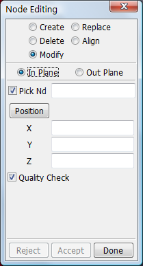
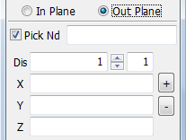
- In Plane
In plane.
- Out Plane
Out plane.
- Pick Nd
Pick node to modify.
- Position
Popup dialog get position.
- X
Enter X coordinate of new position.
- Y
Enter Y coordinate of new position.
- Z
Enter Z coordinate of new position.
- Quality Check
Check element quality when modifying node.
- Reject
Reject last modify node.
- Accept
Accept modified nodes.
- Done
Exit this interface.
- Pick Nd
Define points by node and pick nodes to align.
- Dis
Input distance.
- X
Enter X coordinate of new position.
- Y
Enter Y coordinate of new position.
- Z
Enter Z coordinate of new position.
The main purpose of this interface is to provide various mesh quality check and repair functions in one central area. Single element creation for various element types is available, and splitting of shells using various schemes is available for quick repair of an existing mesh.
- Check
Check elements interface.
- Create
Create elements interface.
- Delete
Delete elements interface.
- Split/Merge
Split/merge shell elements interface.
- Modify
Modify elements interface.
- Direction
Element orientation (default material direction, AOPT=0) interface.
- Composite
Create/modify *ELEMENT_SHELL_COMPOSITE elements.
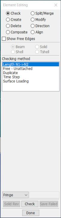
- Show Free Edges
Find and show free edges.
- Beam
Check beam elements.
- Shell
Check shell elements.
- Solid
Check solid elements.
- Tshell
Check tshell elements.
- Fringe
Display results option.
- Solid Rev
Change node order in solids.
- Check
Press to perform checking.
- Save Failed
Save elements to general selection buffer.
- Done
Exit this interface.
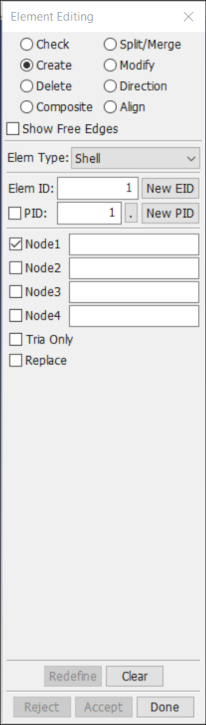
- Elem Type
Selete element type(Beam/Shell/Solid/Tetra/Hexa/Discrete) to create.
- Elem Id
Input element id.
- New EID
Get new default element ID.
- PID
Pick part id.
- New PID
Get new default part id.
- NODE1
Pick node on model to define node 1.
- NODE2
Pick node on model to define node 2.
- NODE3
Pick node on model to define node 3.
- NODE4
Pick node on model to define node 4.
- Tria Only
Create triangle elements only.
- Replace
Replace an existing shell element.
- Redefine
Create nodes and put into temporary buffer.
- Clear
Clear all fields and set default new node id.
- Reject
Commit created nodes and clear them from screen.
- Accept
Commit created nodes and clear all of them from screen.
- Done
Exit this interface.
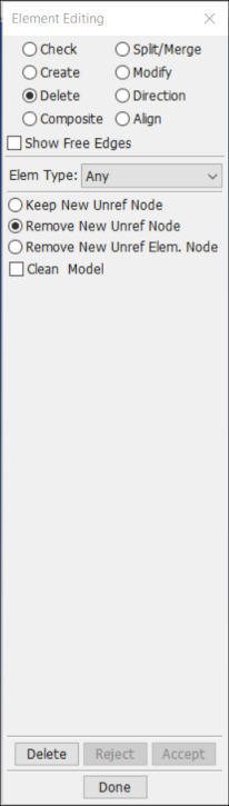
- Elem Type
Selete element type to delete.
- Remove Unref Node
Remove unreferenced nodes.
- Delete
Delete elements.
- Reject
Reject deletion(reset).
- Accept
Make deletion permanant.
- Done
Exit this interface.
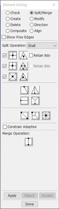

Pick element at dot to define split location.

Pick element at dot to define split location.

Pick element at dot to define split location.

Pick element at dot to define split location.

Pick element at dot to define split location.

Pick element at dot to define split location.

Pick element at dot to define split location.

Pick element at dot to define split location.

Pick element at dot to define split location.

Pick element at dot to define split location.

Pick element at dot to define split location.
- Apply
Apply split elements.
- Reject
Reject last split elements.
- Accept
Accept all split elements.
- Done
Exit this interface.
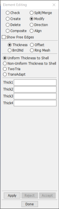
- Add Thickness to Shell
Change two triangle.
- Two Tria
Change two triangle.
- Quality Check
Check element quality when modifying element.
- Thick1
Input first thickness value.
- Thick2
Input second thickness value.
- Thick3
Input third thickness value.
- Thick4
Input fourth thickness value.
- Apply
Apply modified elements.
- Reject
Reject last modified elements.
- Accept
Accept all modified elements.
- Done
Exit this interface.
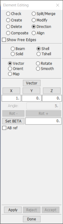
- Shell
Set default material directon for shell elements.
- Vector
Orientate elements by vector.
- Solid
Set default material directon for solid elements.
- Rotate
Incrementally totate element orientation.
- Vector
Rotate orientation by increment in positive direction.
- X
X component of vector.
- Y
Y component of vector.
- Z
Z component of vector.
- Angle
Increment angle for psi(degrees).
- Rot-
Increment psi in negative direction.
- Rot+
Increment psi in positive direction.
- Set PSI
Explicitly set psi angle value for selected elements.
- AB ref
Use Airbag Reference Geometry as base geometry.
- Apply
Apply orientation by vector.
- Reject
Reject the modified element orientations.
- Accept
Accept the modified element orientations.
- Done
Exit this interface.
Direction -> Solid and Vector
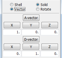
- A-vector
A-vector for solid _ortho.
- X
X component of A-vector.
- Y
Y component of A-vector.
- Z
Z component of A-vector.
- D-vector
D-vector for solid _ortho.
- X
X component of D-vector.
- Y
Y component of D-vector.
- Z
Z component of D-vector.
Direction -> Solid and Rotate
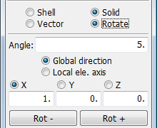
- Angle
Increment angle for psi(degrees).
- Global direction
Rotate about element global axis.
- Local ele. axis
Rotate about element local axis.
- X
X component of rotation vector.
- Y
Y component of rotation vector.
- Z
Z component of rotation vector.
- Rot-
Rotate orientation by increment in negative direction.
- Rot+
Rotate orientation by increment in positive direction.
*ELEMENT_SHELL_(OFFSET_)COMPOSITE is created/modified within this interface. Each ply represent an integration point. Tapered layups (when a ply is not covering the whole part) can be created by setting a very small thickness and a *MAT_NULL material at locations where a certain ply does not exist. In this way a whole physical ply can be evaluated over the complete part by selecting the desired integration point.
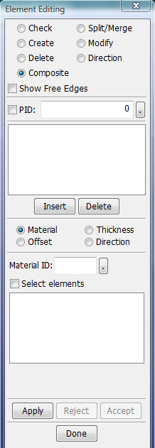
- PID
Active part to operate on. Pick, type in or select part from list. Only one part is active at any singe time.
- Insert
Insert a new ply below the currently selected. Select none to insert at first position.
- Delete
Delete selected plies for selected elements.
Composite -> Material
- Material ID
Type in material ID or select it from list.
- Select Elements
Put elements that match selected plies and materials in to selection buffer.
- Apply
Apply the material ID to selected plies and elements.
Composite -> Thickness
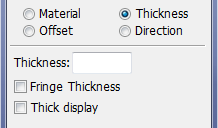
- Thickness
Enter the thickness to be applied to selected plies.
- Fringe Thickness
Fringe plot the total thickness for selected layers.
- Thick display
Display the layup for each element as blocks.
- Apply
Apply the thickness to selected plies and elements.
Composite -> Offset
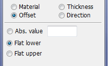
- Abs. value
Enter the absolute value for the offset.
- Flat lower
Let LSPP compute the currently total thickness and apply an offset that locate the nodes at the bottom surface of the stack.
- Flat upper
Let LSPP compute the currently total thickness and apply an offset that locate the nodes at the upper surface of the stack.
- Apply
Apply the offset based on the above selection to the currenly selected plies and elements.
Composite -> Direction -> Vector
Unmodified ply direction: The vector N1->N2 is drawn with a red arrow
Modified ply direction: The vector N1->N2 rotated Bi degrees is drawn with a green arrow
Modified ply direction: The vector N1->N2 rotated Bi + BETA degrees is drawn as a blue arrow. BETA is the angle from the _BETA keyword option.
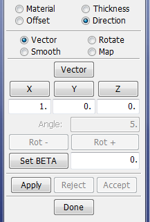
- Vector
Brings up the vector selection interface.
- X,Y,Z
Set the direction to {1,0,0}, {0,1,0} and {0,0,1} respectively in the direction fields below.
- Set BETA
Set the material angle to a specified value.
- Apply
Apply the direction from the text fields above to selected plies and elements. The vector will be projected on to each element in the element normal direction and the material angle will be computed and applied to the keyword.
- Accept/Reject
Accept or reject the smoothed ply directions.
Composite -> Direction -> Rotate
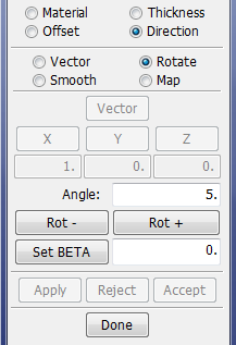
- Angle
Angle increment to rotate.
- Rot +/-
Rotate the direction for selected plies and elements "Angle" degrees about positive or negative element normal direction.
- Accept/Reject
Accept or reject the rotated ply directions.
Composite -> Direction -> Smooth
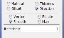
- Iterations
Number of smooth iterations to be performed.
- Apply
Perform smoothing of directions on selected plies and elements by applying the average direction of all attached elements.
- Accept/Reject
Accept or reject the smoothed ply directions.
Composite -> Direction -> Map
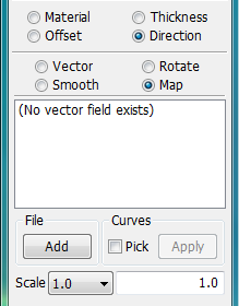
- File Add
Create a direction vector by adding from (.dvm) file defined as vectors at discrete points.
The format of the file is simply a text file with one line for each coordinate (xc, yc, zc) and the vector (xd, yd, zd) at this point:
x1c y1c z1c x1d y1d z1d
x2c y2c z2c x2d y2d z2d
.
.
.
- Curves
Create a vector field from geometric curves.
- Pick
Activate picking of curves.
- Apply
Create the vector field from selected curves.
- Scale
Scale factor for the displayed vectors from the file.
- Apply
Apply the selected discrete vector field map to the selected plies and elements as the directions of those items. This uses the vector that is closest to each element. The vector is then projected onto the element in the element's normal direction, and the corresponding ply angle is computed and applied to the shell.
- Accept/Reject
Accept or reject the smoothed ply directions.
This interface is used to create and modify FEM NURBS element.
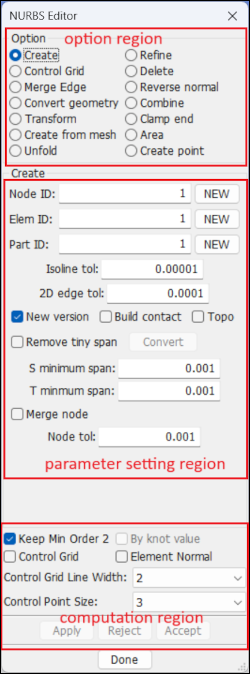
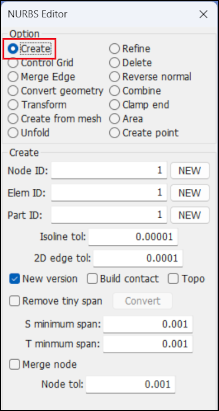
Option region: Option for NURBS 2D element creation or editing.
Create: Create NURBS 2D element by selecting NURBS surface geometry.
Refine: Select NURBS 2D element to refine.
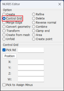
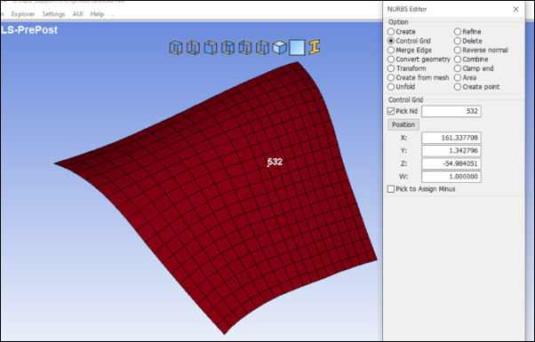
Control Grid: view coordinates of NURBS 2D patch control points.
Merge Edge: Merge the common edge between two adjcent NURBS elements.
Reverse normal: Select NURBS 2D elements and reverse their normal.
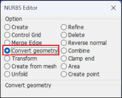
Convert geometry: Convert NURBS 2D element into geometry.
Combine: Combine multiple elements into one element.
Transform: There are 4 methods to transform NURBS 2D patch: rotate, scale, translate and copy.
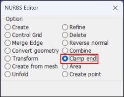
Clamp end: Clamp the knot vector of NURBS 2D patch.
Create from mesh: Create NURBS 2D patch from mesh.
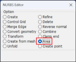
Area: Calculate area of NURBS 2D element.
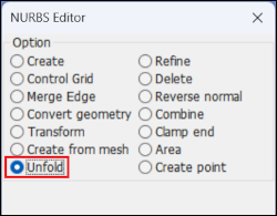
Unfold: Unfold NURBS 2D patch from 3D to 2D plane.
Create point: Pick a point on NURBS 2D patch and calculate the parameter coordinate (u,v) of the point.
Parameter setting region: Setting parameter values in the case of every option.
Computation region: This region is share for all options.
Keep Min Order 2: if this button is checked, the element degree will be checked, in case that the degree in S-direction or t-direction is smaller than 2, the degree will be raised to be 2.
By knot value: this button is use for 'Refine' option only. If this button is checked, all refinement operation is done in 2D domain. Otherwise, all refinement operation is done in 3D physical position.
Control grid: checked this button to show the control point grid.
Element normal: check this button to show the element normal.
Control grid line width: this is for controlling the width of control grid line displaying.
Control point size: this is for controlling the size of control point dsiplaying.
Apply: click this button for computation and preview the result.
Reject: reject the previewed result.
Accept: accept the result and add it into database.
- Create
To create the NURBS element, do the following:
Select radio button 'Create' in 'Option' group.
Select NURB Surface geometry.
Set parameter vlaue for NURBS element creation.
Click 'Apply' to preview the NURBS element.
Click 'Accept' to add the element into database.
Parameter settings:
'Isoline tol': tolerance threshold for detecting if the 2d trimming curve is an isoline in S-direciton or T-direction '2D edge tol': tolerance threshold for 2d edge line 'Build contact': this button is used for he case of multiple nurbs elements creation. If this button is checked, the contact topology data will be created and added into keyword card. 'Remove tiny span': if this button is checked, the tiny span in knot vector will be detected and removed. 'S minimum span': the threshold value for removing tiny span in S knot vector. If the span length is smaller than the specified value, the span will be removed. 'T minimum span': the threshold value for removing tiny span in T knot vector. If the span length is smaller than the specified value, the span wil be removed in T knot vector. 'Merge node': if this button is checked, the overlapped nodes will be detected and merged. 'Node tol': the threshold for overlapped node dectection. - Control Grid
Pick a control point to view its coordinates (x, y, z, w).
- Merge Edge
Merge common edge shared by 2 NURBS elements.
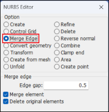
Edge gap: tolerance threshold for detecting if the common edge can be merged.
- Convert geometry
Convert NURBS element into geometry.
- Transform
Rotate, scale, translate, or copy the NURBS element.
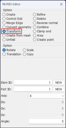
Rotate: Rotate NURBS 2D patch around a specified axis. User can select X-axis, Y-axis, Z-axis and vector as axis for rotation.
Scale: Scale NURBS 2D patch by the specified number.
Translation: Translate NURBS 2D patch to a new place.
Copy: Copy NURBS 2D patch.
- Create from mesh
Create NURBS 2D patch from mesh. Picks a mesh and create a new NURBS 2D patch approximating the mesh.
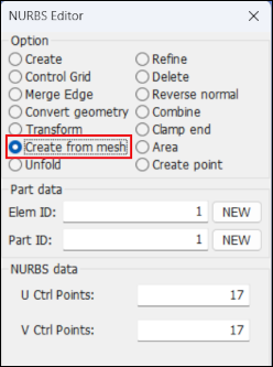
U Ctrl Points: number of control point in u-direction
V Ctrl Points: number of control point in v-direction
- Unfold
Unfold NURBS 2D patch from 3D to 2D plane.
- H-Refine
Refine NURBS element by using the 'H-refinement' method. Select the radio button 'Refine' in option region and select radio button 'H-Refinement' in parameter setting region.

Keep geometry: if this button is checked, the element is refined by symbol operation, otherwise, the element is refined by numerical operation.
Parameter: parameter value setting for H-refinement.
R: parameter values are applied in R-direction.
S: parameter values are applied in S-direction.
Degree: this is disabled in 'H-Refinement'.
span: average length of span for H-refinement.
segment: this is disabled in 'H-Refinement'.
- P-Refine
Refine NURBS element by using he method of 'P-refinement'. User selects radio button 'Refine' in option region and select radio button 'P-Refinement' in parameter setting region.
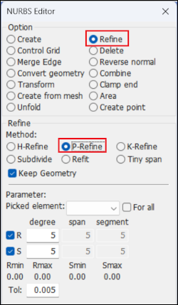
Keep geometry: if this button is checked, the element is refined by symbol operation, otherwise, the element is refined by numerical operation.
Parameter: parameter value setting for h-refinement.
R: parameter values are applied in R-direction.
S: parameter values are applied in S-direction.
Degree: element degree number.
span: this is disabled.
segment: this is disabled.
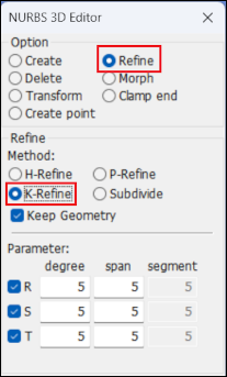
- K-Refine
Refine NURBS element by using he method of 'K-refinement'. Select the radio button 'Refine' in the option region and select radio button 'K-Refinement' in parameter setting region.
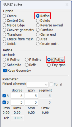
Keep geometry: if this button is checked, the element is refined by symbol operation, otherwise, the element is refined by numerical operation.
Parameter: parameter value setting for h-refinement.
R: parameter values are applied in R-direction.
S: parameter values are applied in S-direction.
Degree: element degree number.
span: average length of span for h-refinement.
Segment : this is disabled for 'K-Refinement'.
- Refine-Subdivide
Refine NURBS element by using he method of 'Subdivide'. User selects radio button 'Refine' in option region and select radio button 'Subdivide' in parameter setting region.
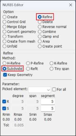
Keep geometry: if this button is checked, the element is refined by symbol operation, otherwise, the element is refined by numerical operation.
Parameter: parameter value setting for h-refinement.
R: parameter values are applied in R-direction.
S: parameter values are applied in S-direction.
Degree: this is disabled. 'span': this is disabled.
Segment : an integer number for how many equivalent span will be created in element.
- Refine-Refit
Refine NURBS element by using he method of 'Refit'. User selects radio button 'Refine' in option region and select radio button 'Refit' in parameter setting region.
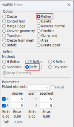
Keep geometry: this button is disable, the element is refitted by numerical operation.
Parameter: parameter value setting for h-refinement.
R: parameter values are applied in R-direction.
S: parameter values are applied in S-direction.
Degree: element degree number.
span: this is disable.
segment: an integer number for how many equivalent span will be created in element.
- Refine-Tiny span
Refine NURBS element by using he method of 'Tiny span '. User selects radio button 'Refine' in option region and select radio button 'Tiny span ' in parameter setting region.
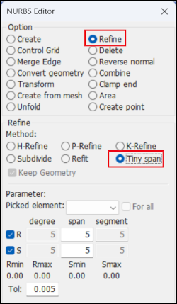
Keep geometry: this button is disabled.
Parameter: parameter value setting for h-refinement.
R: parameter values are applied in R-direction.
S: parameter values are applied in S-direction.
Degree: this is disabled.
span: average length of span for h-refinement.
segment: this is disabled.
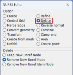
- Delete
Remove the NURBS element.
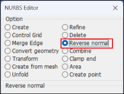
- Reverse normal
Reverse NURBS element normal.
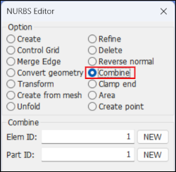
- Combine
Combine multiple NURBS elements into a single element.
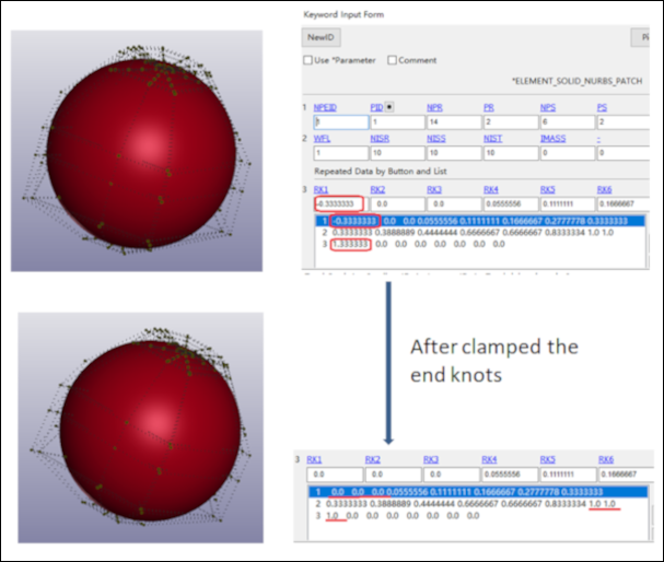
- Clamp End
Clamp the knot vector of NURBS 2D patch. For example, if a NURBS 2D patch has knot vector {-2, -1, 0, 1, 2, 3, 4} on u-direction and the degree is 2, after clamped, the knot vector is {0,0,0, 1, 2, 2, 2}.
- Area
Calculate and display the NURBS 2D element area.
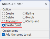
- Create point
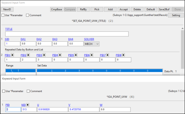
Create entity *IGA_POINT_UVW on NURBS 2D element. If the button ‘Add the point to set’ is checked, the new created *IGA_POINT_UVW will be added to the entity *SET_IGA_POINT_UVW. If the button ‘Add the point to set’ is unchecked, the new *IGA_POINT_UVW will be unreferenced.
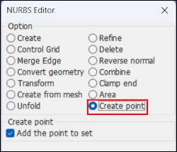
To create *IGA_POINT_UVW on a NURBS 2D patch, user click one location on a patch and click , the *IGA_POINT_UVW shows, click to save the point into database. The point label will be added in the GUI tree.
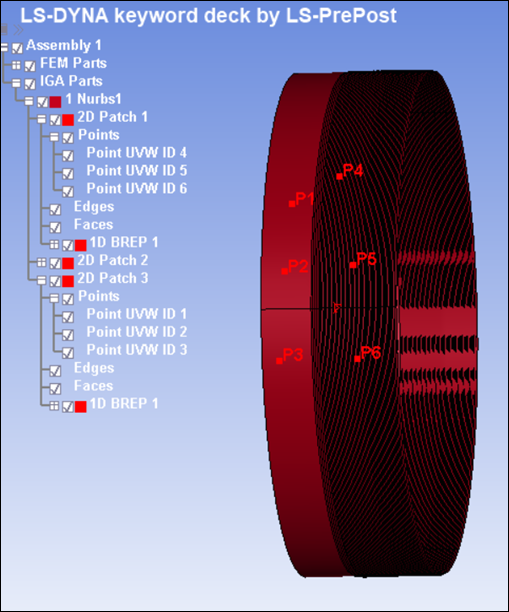
The (U, V, W) coordinates of the point are viewable in the keyword card.
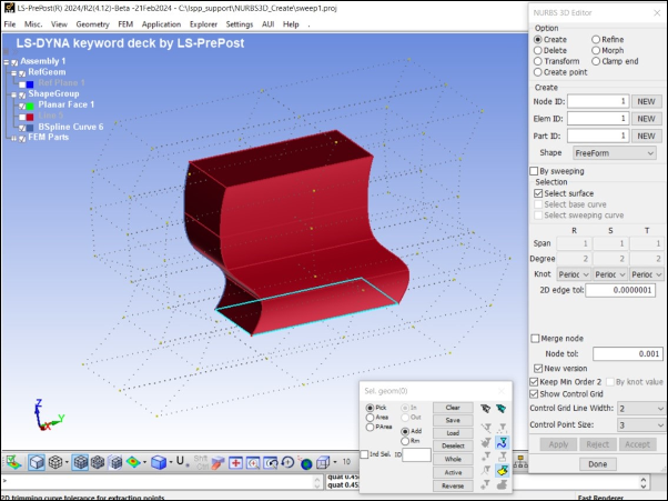
This interface is used to create and modify FEM NURBS 3D entity.
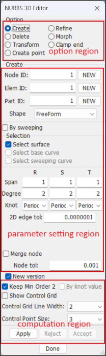
Option region: Option for NURBS 3D element creation or editing.
Create: Create NURBS 3D element by selecting NURBS surface geometry.
Refine: Select NURBS 3D element to refine.
Morph: Select NURBS 3D element, select control point to morph it.
Transform: Transform the selected NURBS 3D element.
Delete: Delete the selected NURBS 3D element.
Clamp end: Change the selected NURBS 3D element to be clamped on the end of knot vector.
Parameter setting region: Setting parameter values in the case of every option.
Computation region: This region is shared for all options.
Keep Min Order 2: If this button is checked, the element degree will be checked, in case that the degree in S-direction or t-direction is smaller than 2, the degree will be raised to be 2. 'By knot value': this button is use for 'Refine' option only. If this button is checked, all refinement operation is done in 2D domain. Otherwise, all refinement operation is doen in 3D physical position.
Show Control Grid: Check this button to show the control point grid.
Element normal: Check this button to show the element normal.
Control grid line width: This controls the display width of the control grid lines.
Control point size: This controls the display size of control points.
Apply: Click this button for computation and preview the result.
Reject: Reject the previewed result.
Accept: Accept the result and add it into database.
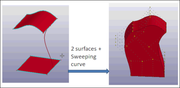
- Create
Create a 3D NURBS element.
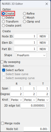
To Create NURBS 3D element:
Select radio button 'Create' in 'Option' group.
Check the box for 'By sweeping', check the button 'Select surface' and select 1 or 2 NURB Surface geometry.
Check the box for 'Select sweeping curve', select a curve for the ridge.
Click button 'Apply' to preview the NURBS element and click button' Accept' to add the element into database.
- Parameter setting
- 2D edge tol
Tolerance threshold for 2d edge line.
- Merge node
If this button is checked, overlapped nodes will be detected and merged.
- Node tol
The threshold for overlapped node dectection.
- NURBS 3D element creation.
'Create' selected
Property value can be set by using ‘Span’, ‘Degree’, ‘Knot’ property during element creation.
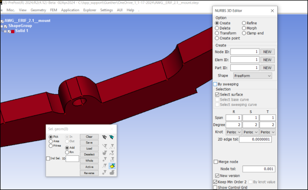
IGA entity can be displayed in the GUI tree after .k file was imported or 3D element was created.
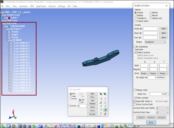
Activate Periodic property for ‘free-form’ and ‘sweeping’ NURBS 3D creation.
- H-Refine
Refine NURBS element by using he method of 'H-refinement'. User selects radio button 'Refine' in option region and select radio button 'H-Refinement' in parameter setting region.
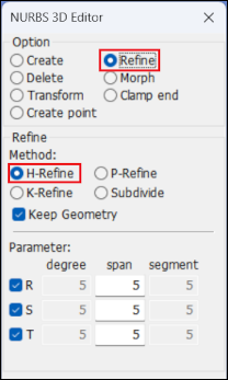
Keep geometry: if this button is checked, the element is refined by symbol operation, otherwise, the element is refined by numerical operation.
Parameter: parameter value setting for h-refinement.
R: parameter values are applied in R-direction.
S: parameter values are applied in S-direction.
Degree: this is disabled in 'H-Refinement'.
span: average length of span for h-refinement.
segment: this is disabled in 'H-Refinement'.
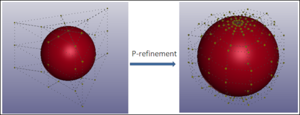
- P-Refine
Refine NURBS element by using he method of 'P-refinement'. User selects radio button 'Refine' in option region and select radio button 'P-Refinement' in parameter setting region.
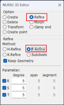
Keep geometry: if this button is checked, the element is refined by symbol operation, otherwise, the element is refined by numerical operation.
Parameter: parameter value setting for h-refinement.
R: parameter values are applied in R-direction.
S: parameter values are applied in S-direction.
Degree: element degree number.
span: this is disabled.
segment: this is disable.
- K-Refine
Refine NURBS element by using he method of 'K-refinement'. Select the 'Refine' radio button in the option region and select radio button 'P-Refinement' in parameter setting region.
Keep geometry: if this button is checked, the element is refined by symbol operation, otherwise, the element is refined by numerical operation.
Parameter: parameter value setting for h-refinement.
R: parameter values are applied in R-direction.
S: parameter values are applied in S-direction.
Degree: element degree number.
Span: average length of span for h-refinement.
Segment: this is disabled for 'K-Refinement'.
- Refine-Subdivide
Refine NURBS element by using he method of 'Subdivide'. User selects radio button 'Refine' in option region and select radio button 'Subdivide' in parameter setting region.
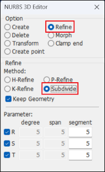
Keep geometry: if this button is checked, the element is refined by symbol operation, otherwise, the element is refined by numerical operation.
Parameter: parameter value setting for h-refinement.
R: parameter values are applied in R-direction.
S: parameter values are applied in S-direction.
Degree: this is disable.
span: this is disable.
segment: an integer number for how many equivalent span will be created in element.
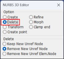
- Delete
Remove the 3D NURBS element.
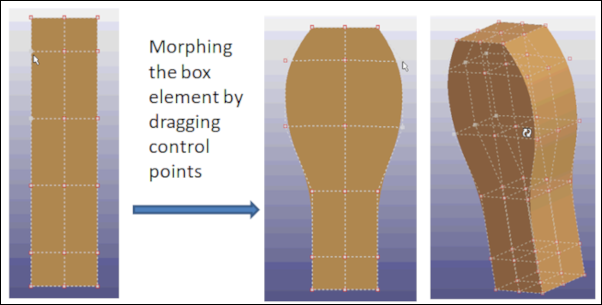
- Morph
Morph NURBS 3D patch by dragging control points.
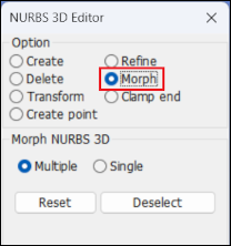
Multiple: pick multiple control points and drag them at same time for morphing;
Single: pick a single control point and drag it for morphing;
Reset: set the morphed NURBS 3D patch to the original position;
Deselect: set the picked control points to be un-selected.
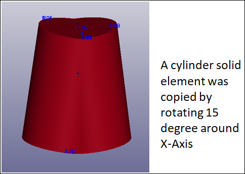
- Transform
Refine NURBS element by using he method of 'Tiny span '. User selects radio button 'Refine' in option region and select radio button 'Tiny span ' in parameter setting region.
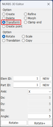
Rotate: create a new NURBS 3D patch by rotating the original one around an axis. The axis can be defined as ‘X-Axis’, ‘Y-Axis’, ‘Z-Axis’ or other vector.
Scale: create a new NURBS 3D patch by scaling the original one.
Translate: create a new NURBS 3D patch by translating the original one.
Copy: create a new NURBS 3D patch by copying the original one.
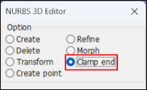
- Clamp end
Clamp the knot vector of NURBS 3D patch. For example, if a NURBS 3D patch has knot vector {-2, -1, 0, 1, 2, 3, 4} on u-direction and the degree is 2, after clamped, the knot vector is {0,0,0, 1, 2, 2, 2}.
- Create point
Create entity *IGA_POINT_UVW on NURBS 3D element. If the button ‘Add the point to set’ is checked, the new created *IGA_POINT_UVW will be added to the entity *SET_IGA_POINT_UVW. If the button ‘Add the point to set’ is unchecked, the new *IGA_POINT_UVW will be unreferenced.
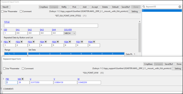
To create *IGA_POINT_UVW on a NURBS 3D patch, user click one location on a patch and click ‘Apply’ button, the *IGA_POINT_UVW shows, user click ‘Accept’ button to save the point into database. The point label will be added in the GUI tree.
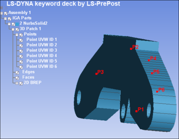
The (U, V, W) coordinates of the point can be seen in keyword card.
This interface is for modifying model or part mass properties to obtain desired mass, center of mass, and inertia.
- Current
Measure the current mass, center of mass, and inertia properties (which serve as starting reference values).
- Desired
Assign desired mass properties using one of two methods: (1) add *ELEMENT_MASS to selected nodes or (2) convert *PART to *PART_INERTIA (if necessary) and assign specified properties.
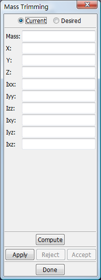
- Mass
Desired mass.
- X
X-coordinate for current center of gravity.
- Y
Y-coordinate for current center of gravity.
- Z
Z-coordinate for current center of gravity.
- Ixx
Current Ixx component for mass moment of inertia.
- Iyy
Current Iyy component for mass moment of inertia.
- Izz
Current Izz component for mass moment of inertia.
- Ixy
Current Ixy component for mass moment of inertia.
- Iyz
Current Iyz component for mass moment of inertia.
- Ixz
Current Ixz component for mass moment of inertia.
- Compute
Automatically fill in mass properties for VISIBLE entities.
- Apply
Apply mass trim.
- Reject
Reject mass trim.
- Accept
Accept mass trim.
- Done
Exit mass trim interface.
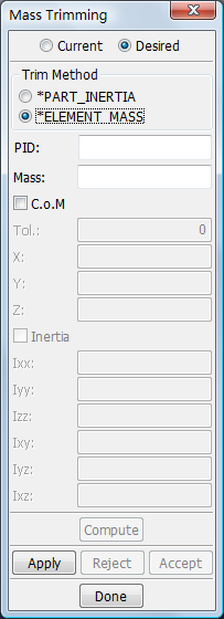
- *PART_INERITA
Select ONE rigid body part to use as *PART_INERTIA to obtain desired properties.
- *ELEMENT_MASS
Select nodes to generate *ELEMENT_MASS on, trying to obtain desired properties.
- Include
Are mass and inertia for the selected part included in Current properties.
- PID
Optionally enter part ID for generated mass elements.
- MASS
Desired mass.
- C.o.M
Optionally modify Center of Mass.
- Tol.
Acceptable deviation to the desired center of mass.
- X
X-coordinate for desired center of gravity.
- Y
Y-coordinate for desired center of gravity.
- Z
Z-coordinate for desired center of gravity.
- Inertia
Optionally modify mass moment of inertia.
- Ixx
Desired Ixx component for mass moment of inertia.
- Iyy
Desired Iyy component for mass moment of inertia.
- Izz
Desired Izz component for mass moment of inertia.
- Ixy
Desired Ixy component for mass moment of inertia.
- Iyz
Desired Iyz component for mass moment of inertia.
- Ixz
Desired Ixz component for mass moment of inertia.
This interface is used for generating spotweld elements from a file containing hundreds or thousands of weld locations, and can generate both solid and beam type 9 spotweld elements, in doing so automatically creates the following keywords: *PART, *SECTION, *SET_NODE, *SET_PART, *MAT_SPOTWELD, *HOURGLASS, and *CONTACT_SPOTWELD.
- Sample
Click here to find more regarding Spotweld.
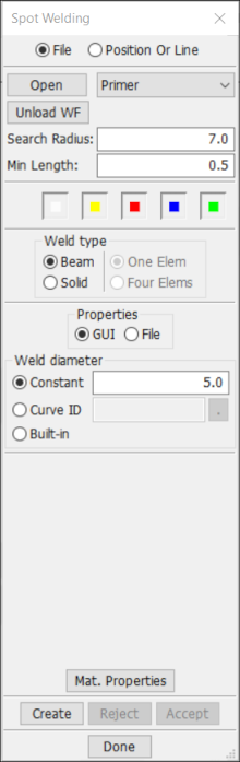
- Open
Load spotweld file.
- Primer
Select spotweld file format(Primer, Master Weld File, XML, Custom).
- Unload WF
Delete weld info. Weld elements will NOT be deleted.
- Search radius
Radius to search for elements to connect with weld element.
- Min Length
Min length for weld elements.

Display weld data.

Display welds which will be smaller than Min Length.

Display welds which will fail being created.

Display welds which will be sucessfully created.

Display welds which have been successfully created.
- Beam
Create Beam element for the welds.
- Solid
Create Solid element for the welds.
- One Elem
Enter x/y/z-coordinates of minimum and maximum point.
- Four Elems
Enter number of elements along x/y/z.
- GUI
Set properties from GUI.
- File
Set properties from file.
- Constant
Constant diameter for weld.
- Curve ID
Diameter as function of min sheet thickness (DEFINE_CURVE ID).
- Built-in
Diameter = 5.*sqrt(min_thickness).
- Mat. Properties
Set material properties.
- Create
Create spotweld.
- Reject
Reject the previewed spotwelds.
- Accept
Accept the previewed spotwelds.
- Done
Exit spotweld generation interface.
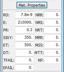
- RO
Density.
- E
Young's modulus.
- PR
Poisson's ratio.
- SIGY
Initial yield stress.
- ET
Hardening modulus.
- DT
Time step size for mass scaling.
- TFAIL
Failure time if nonzero.
- EFAIL
Effective plastic strain at failure.
- NRR
Axial force resultant at failure, rr direction.
- NRS
Axial force resultant at failure, rs direction.
- NRT
Axial force resultant at failure, rt direction.
- MRR
Torsional moment resultant at failure, rr direction.
- MSS
Moment resultant at failure, ss direction.
- MTT
Moment resultant at failure, tt direction.
- NF
Number of force vectors stored for filtering.
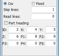
- Csv
Read comma separated file.
- Fixed
Read file with fixed field width.
- Skip lines
Skip this number of lines in the beginning of file.
- Raad lines
Read this number of lines after \"Skip lines\". 0 = End Of File.
- Part heading
Use part HEADING instead of part ID for PIDx fields.
- ID
Field index for weld ID (not mandatory). Zero is permitted.
- Z
Field index for Z coordinate.
- P3
Field index for LS_DYNA part ID to connect with this weld.
- X
Field index for X coordinate.
- P1
Field index for LS_DYNA part ID to connect with this weld.
- P4
Field index for LS_DYNA part ID to connect with this weld.
- Y
Field index for Y coordinate.
- P2
Field index for LS_DYNA part ID to connect with this weld.
- P5
Field index for LS_DYNA part ID to connect with this weld.
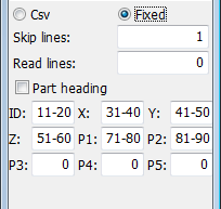
- ID
Columns for weld ID (not mandatory). Single zero is permitted.
- Z
Columns for Z coordinate.
- P3
Columns for LS_DYNA part ID to connect with this weld.
- X
Columns for X coordinate.
- P1
Columns for LS_DYNA part ID to connect with this weld.
- P4
Columns for LS_DYNA part ID to connect with this weld.
- Y
Columns for Y coordinate.
- P2
Columns for LS_DYNA part ID to connect with this weld.
- P5
Columns for LS_DYNA part ID to connect with this weld.
This interface is used to generate particles for SPH modeling. Box, Sphere, Cylinder, Cone, and ShellVolume: SPH Mass = Den*Pitch^3 (where Den = User Specified Density).
NOTE: The Fill% option creates a "partial fill" which means filling up the body with MASS (not filling up to a specified volume percentage). So for the SolidNodes method, if the solid mesh is not of constant element size, it may look odd, and the density of the SPH part will not be what has been specified. For all other methods, it will fill up to the given percentage of both mass and volume.
- Box
Generate SPH in user defined box.
- Sphere
Generate SPH in user defined Sphere.
- Cylinder
Generate SPH in user defined Cylinder.
- Cone
Generate SPH in user defined Cone.
- SolidCenter
SPH particles are created in the center of each solid element, and the mass for each SPH element will be EleVol*Den (where EleVol = Volume of Each Solid Element and Den = User Specified Density).
- SolidNodes
SPH particles are created at existing solid element nodes. The mass for every SPH element will be constant and equal to Vol*Den/N (where Vol = Total Volume of Solid Elements, Den = User Specified Density, N = Number of Solid Element Nodes).
- ShellVolume
The body to be filled must consist of a "water tight" volume of shell element (with no free edges). However, shells normals do not need to be consistent.
- Sample1
Show how to create Sph with Box method.
- Sample2
Show how to create Sph with ShellVolume method.
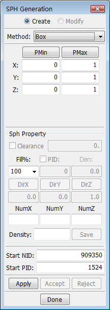
- Method
Select method to create SPH elements.
- Clearance
Leave gap between SPH nodes and elements.
- Fill%
Fill volume level(%).
- PID
Enter part Id for the unfilled particles (if needed).
- Den
Enter density of the unfilled portion (if needed).
- DirX
Set fill direction in X.
- DirY
Set fill direction in Y.
- DirZ
Set fill direction in Z.
- NumX
No. of particles in X direction or radial direction).
- NumY
No. of particles in Y direction or radial direction).
- NumZ
No. of particles in Z direction or radial direction).
- Density
Enter density of the unfilled portion (if needed).
- Save
Save or replace sph property for each selected part.
- Start Nd ID
Enter starting node Id for the SPH nodes.
- Start Part ID
Enter part Id for the SPH part.
- PMin
Click to activate Position Dialog for min. coordinates.
- PMax
Click to activate Position Dialog for max. coordinates.
- X
Enter X coordintate for min. or max. coordinate point.
- Y
Enter Y coordintate for min. or max. coordinate point.
- Z
Enter Z coordintate for min. or max. coordinate point.
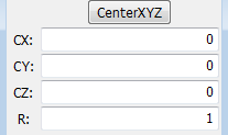
- CenterXYZ
Click to activate Position Interface for center coordinates.
- CX
Enter X coordintate for center of the sphere.
- CY
Enter Y coordintate for center of the sphere.
- CZ
Enter Z coordintate for center of the sphere.
- R
Enter Radius of the sphere.
- Position
Activate Position Interface for base point center of cylinder or cone.
- X
Enter X coordintate for base point of the cylinder or cone.
- Y
Enter Y coordintate for base point of the cylinder or cone.
- Z
Enter Z coordintate for base point of the cylinder or cone.
- Direction
Activate Direction Dialog for direction of cylinder.
- DX
Set direction X with 1 or -1.
- DY
Set direction Y with 1 or -1.
- DZ
Set direction Z with 1 or -1.
- R
Enter radius of cylinder or cone.
- Len
Enter length of cylinder or cone.
- R2
Enter end point radius of cone.
- Polar
Generate particals in polar coord. system.
Use this interface to convert between Multiple Solver mesh and mesh.
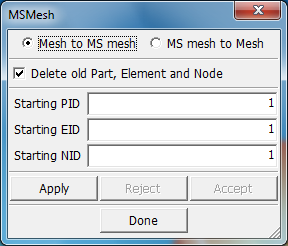
- Mesh to MSMesh
Convert mesh to MSMesh.
- MS mesh to Mesh
Convert MSMesh to Mesh.
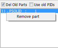
- Delete old Part,Element and Node
decide whether or not to delete old part ,element and node.
- Starting PID
Enter starting part ID.
- Starting EID
Enter starting element ID.
- Starting NID
Enter starting node ID.
- Apply
Apply selected conversion.
- Reject
Reject the convert operation.
- Accept
Accept the conversation.
- Done
Exit MSMesh interface.
This interface is used for mapping *INITIAL_STRESS, including plastic strain, shell thickness and history variables, from one part to another geometrically overlapping part. Here is a detailed description for each map option:
- Shell to Solid mapping
The coordinate for each solid element integration point will be projected on to the closest shell element. This will be the shell element from which the results will be mapped from.
In order to map from a shell to solid element part, you must specify the two topological sides on the solid part(s) that correspond to the upper and lower surface of the shell elements. These are called "Side 1" and "Side 2" in the interface below.
A parametric position beween "Side 1" and "Side 2" will then be computed for each integration point in the solid elements. Data from the through-thickness shell integration point which best matches this parametric position will be selected for mapping of the results.
If the shell has four in-plane result values, an inter- or extrapolated value will be computed at the point on the shell which is closest to the solid element integration point. This inter/extrapolated value will be assigned to the solid element integration point. Meaning that it can actually become larger than the largest of the four shell in-plane values, or smaller than the smallest. Plastic strain will however never be extrapolated to a negative value. Only stress and plastic strain are interpolated, not history variables. History variable values will be assigned from the closest integration point.
- Solid to Solid mapping
The integration point to map to can either be inside or outside the solid elements with results. If it's outside, the closest point on the closest element will be found. The stresses and plastic strain will be inter/extra-polated to this location and the value will be assigned to the integration point. History variable values will be assigned from the closest integration point, they will not be interpolated or extrapolated.
- Shell to Shell mapping
The number of integration points specified on SECTION_SHELL will be used when deciding how many through-thickness integration points will be used for the generated *INITIAL_STRESS keyword. Much like Shell to Solid mapping, the closest parametric coordinate for the through-thickness integration point will be used for assigning the values. In-plane inter/extra-polation is done for the stress and plastic strain. Plastic strain will however never be extrapolated to a negative value. History variable values will be assigned from the closest integration point.
- Solid to Shell mapping
"Side 1" and "Side 2" must be defined for the solid part(s). The *INITIAL_STRESS and thickness can be mapped in two different ways, A and B:
A: If leaving "Target IPs" field empty, the initial_stress results will be mapped to the integration points specified by the *SECTION_SHELL of the shell part and thickness will be applied to *ELEMENT_SHELL_THICKNESS. For each integration point in the shell, the closest points on "Side 1" and "Side 2" will be found. The thickness of the shell will be set to the distance between these two points. The stress will be extracted from the parametric position between "Side 1" and "Side 2" corresponding to the parametric coordinate of the through-thickness shell integration point.
B: Mapping results from a multi-part layered (composite) solid to ELEMENT_SHELL_COMPOSITE can be activated by specifying a list of through-thickness integration point number(s) in the "Target IPs" text field. The thickness between "Side 1" and "Side 2" will be evenly distributed to the specified integration points. The stress results will be extracted from the parametric position between "Side 1" and "Side 2" corresponding to an even distributed of the specified integration points.
In-plane inter/extra-polation is done for the stress and plastic strain. Plastic strain will however not be extrapolated to a negative value. History variable values will be assigned from the closest integration point.
For example, if the solid structure is composed of three parts with two stiff outer skins and a softer core, the mapping to the *ELEMENT_SHELL_COMPOSITE must be made in three steps. The option "Fully integrated" must remain the same for all three mappings as the number of in-plane integration points must remain the same in a *INITIAL_STRESS_SHELL keyword. "Target IPs" must be specified for the three mappings as well to get a mapping to *ELEMENT_SHELL_COMPOSITE. The target integration points are numbered 1 as the first integration point at the bottom and in sequential order to the integration point at the top.
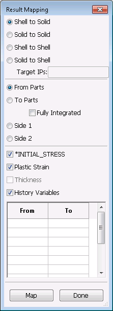
- Shell to Solid
Mesh by number of elements.
- Solid to Shell
Mesh by element size.
- Shell to Shell
Mesh by existing points of line.
- Solid to Shell
Enter or adjust number of elements along line 1.
- Target IPs
Bias radio.
- From Parts
Bias from two end.
- To Parts
Enter or adjust number of elements along line 2.
- Fully Integrated
Enter or adjust number of elements along line 3.
- Side 1
Enter or adjust number of elements along line 4.
- Side 2
Enter or select target part ID.
- *INITIAL_STRESS
Get new default part ID.
- Plastic Strain
Perform meshing.
- Thickness
Accept the created mesh.
- History Variables
Reject the created mesh or the selected lines.
- The "From - To"-table
Exit the nLMesh Interface.
- Map
Perform the map operation.
- Done
Exit result mapping interface.