In this step, you will create an internal Ogrid to improve the angles in the block corners. This is the best method for fixing bad angles in block corners within cylindrical geometry. Ansys ICEM CFD has a specific Ogrid tool to make it easy to accomplish even on complicated geometry. Before proceeding to this step, make sure that your surface vertices are aligned as you want them and internal edges are straight. The Ogrid tool offsets the boundary faces orthogonally and you may end up with twice as many vertices. It is more convenient to adjust your surface blocking to ideal locations before Ogrid rather than after.
Enable Surfaces.
 >
> Create the Ogrid.
> Split Block
 > Ogrid Block
Click
 (Select block(s)) and then
  (Select all appropriate
visible objects) from the selection tool bar.
(Select all appropriate
visible objects) from the selection tool bar.Alternatively, enter
vfor all visible blocks or drag a box to select all blocks.Note: The option
aindicating all is not available for blocking to avoid selection of VORFN blocks, which are not visible, but are still in the model.Click
 (Select face(s)) and select the faces representing
the planar geometry (INL, SYM, OUT). See Figure 60: Blocks and Faces Selected for Ogrid Creation. Click the middle-mouse button
to accept the selection.
(Select face(s)) and select the faces representing
the planar geometry (INL, SYM, OUT). See Figure 60: Blocks and Faces Selected for Ogrid Creation. Click the middle-mouse button
to accept the selection.You can also select the faces using any of the following:
Select
 (Toggle select diagonal
corner vertices) in the Select blocking face toolbar that appears or type
(Toggle select diagonal
corner vertices) in the Select blocking face toolbar that appears or type Shift-Don the keyboard. This will allow you to select two diagonally opposite corners that make up the face.Select
 (Select items in a
part) in the Select blocking face toolbar
that appears or type
(Select items in a
part) in the Select blocking face toolbar
that appears or type Shift-Pon the keyboard. This will open the Select Blocking parts dialog box and will allow you to select the faces.
Retain the default settings and click in the Ogrid Block DEZ.
In Figure 61: Blocking with the Ogrid Structure, the Ogrid passes through the selected faces. The radial blocks are adjacent to the cylinder surfaces.
Modify the Ogrid.
> Edit Block
 > Modify Ogrid
Retain the selection of Rescale Ogrid in the Method drop-down list.
Retain the selection of All Visible for Block Select.
Click
 (Select edge(s)) and select the radial edge
shown in Figure 62: Edge Selected for Modifying the Ogrid.
(Select edge(s)) and select the radial edge
shown in Figure 62: Edge Selected for Modifying the Ogrid.Ensure that Absolute distance is disabled.
Enter
0.5for Offset.Click in the Modify Ogrid DEZ.
Update the surface mesh sizes on the blocking.
> Pre-Mesh Params
 > Update Sizes
Retain the selections of Update All and Run Check/Fix Blocks.
Click in the Recalculate Sizes DEZ.
Enable Pre-Mesh.
> Click in the Mesh dialog box.
Refine the mesh using edge parameters.
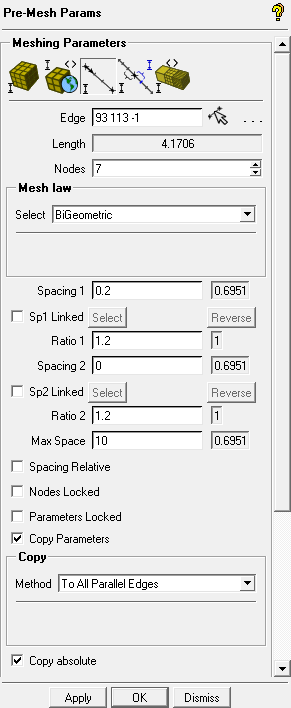
> Pre-Mesh Params
> Edge Params 
Disable Pre-Mesh.
> Click
(Select edge(s)) and select one of the radial
edges.Increase Nodes to
7.Enter
0.2for Spacing 1.Enable Copy Parameters and select To All Parallel Edges in the Method drop-down list.
Enable Copy absolute and click in the Meshing Parameters DEZ.
Enable Pre-Mesh.
> Click in the Mesh dialog box.
Disable Curves and Surfaces under Geometry and Edges under Blocking in the display control tree.
The final mesh is shown in Figure 63: The Final Mesh.