


For automatic mesh generation, a Default Initialization node is automatically created in the Initial Conditions tree. If there is only one region in your simulation domain, then the Default Initialization is sufficient for you.
You may specify constant or spatially varying initial conditions for several solution variables. Refer to Initialization Panel for details.
If there are multiple regions in your simulation domain and you want to specify different initial conditions for them, then you will need to define one or more Secondary Regions. There are two ways to define secondary regions when using automatic mesh generation:
Note that any cells not explicitly identified by the secondary region definition will receive the Default Initialization.
The Initial Conditions icon bar offers the option: Secondary Region from
Material Point  , which can be used to define a new region that will be initialized
differently from the default initialization.
, which can be used to define a new region that will be initialized
differently from the default initialization.
This option is critically useful when you have regions that are disconnected from each other. In internal combustion engine simulations, it is very common that the simulation domain includes engine cylinder, intake and exhaust manifolds or ports that are disconnected, because the intake and exhaust valves are often closed at the beginning. In this case, you must use this option to define a secondary region from material point for each disconnected region and specify their initial conditions respectively.
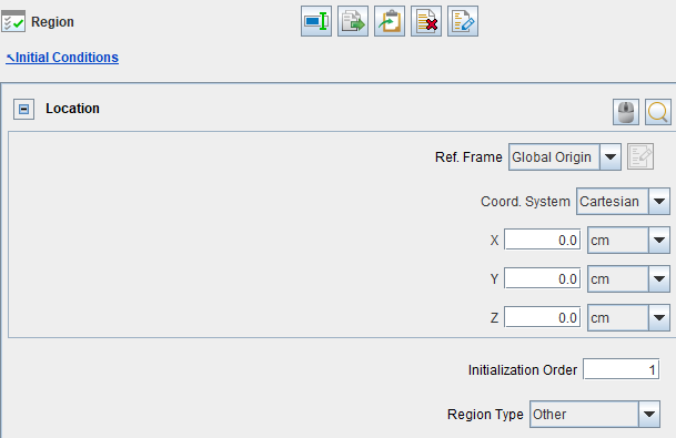
Creating a new Initialization will add an item to the Initial Conditions tree and open an Editor panel to configure the initial conditions of that region. Figure 3.25: New Secondary Region from Material Point shows part of the panel. Here, you need to specify a Location for the Material Point. This is an extra material point different from the default Material Point under Mesh Controls (See Mesh Controls for Automatic Meshing). This new material point must sit inside the watertight surfaces, and touch a cell inside the secondary region.
Important: When there are disconnected regions in the simulation domain, material points are required in each disconnected region so that they are properly meshed with fluid cells. We must use New Secondary Region from Material Point to place new material points into the regions separated from the one hosting the default material point. This is the only way to add extra material points. Failure to place material points into the disconnected regions would prevent them from being meshed and trigger errors.
Once a secondary region is created, then the Initialization Order must be correctly set. Initialization order is used by the meshing library internally and its purpose is as follows: after the simulation starts, when disconnected regions become connected due to boundary motions, the initialization order determines which region should be used in assigning properties in newly created cells. The order (from smaller index to larger index) should generally follow the direction of the flow.
For example, in a four-stroke engine, when new cells are created by the movement of an intake valve, those cells should be initialized from the intake port, and not from the cylinder. It is required that the initialization order of the intake port should be lower than the Initialization order of the cylinder. Similarly, the Initialization order of the cylinder should be lower than the Initialization order of the exhaust port.
So, the initialization order for a four-stroke engine should be:
Intake port
Cylinder
Exhaust port
The following tutorials provide examples of initializing four-stroke engines using New Secondary Region from Material Point:
In a two-stroke engine with side ports that are uncovered by the piston motion, sliding port interfaces separate the engine cylinder from the intake and exhaust ports. Initialization order should be:
Cylinder
Intake port
Exhaust port
The following tutorials provide examples of initializing two-stroke engines using New Secondary Region from Material Point:
The following tutorial provides a usage of New Secondary Region from Material Point in a non-engine case, where regions are disconnected by an injector pintle closure:
In the unusual case that no stationary location exists that stays inside the watertight surface throughout the entire simulation, the material point location can be set to translate along with a moving boundary surface. Use the Translate Material Point with Boundary Motion option on the Initial Conditions panel to specify the boundary that should have paired movement with the material point.
You must specify a Region Type for the new secondary region. For more information, refer to Assigning Region Types.
The panel allows specifying constant or spatially varying initial conditions of several solution variables for this secondary region. For details, refer to Initialization Panel.
The Initial Conditions icon bar offers the
option: Secondary Region from Sub-volume  , which can be used to define a new region that will be initialized
differently from the default initialization. Using this option requires creation of
user-defined sub-volumes under the Geometry node. See
Sub-Volumes for more information and how to specify
them.
, which can be used to define a new region that will be initialized
differently from the default initialization. Using this option requires creation of
user-defined sub-volumes under the Geometry node. See
Sub-Volumes for more information and how to specify
them.
This option is useful when you want to initialize a region that is connected to other region(s), and you want specific initial conditions to apply for this region only. In an engine simulation, this option is typically used to define a subchamber or prechamber attached to an engine cylinder.
Initialization Order is important when using sub-volumes for initial conditions. The rule is that sub-volumes must be given a lower initialization order (which means higher priority) compared to the material point regions. Most often, the material point regions refer to the Default Initialization. So, setting initialization order to 1 for the sub-volume and 2 for the default initialization would work.
Note: This option should not be used to define engine port or manifold regions, which are disconnected to the engine cylinders due to valve closure. Such disconnected regions should be initialized using New Secondary Region from Material Point, because we need the material points to mesh the disconnected regions. Failure to do so can lead to incorrect region IDs for cells near the port/cylinder interface. These errors are difficult to notice and cause problems in the calculations.
You must specify a Region Type for the new secondary region. For more information, refer to Assigning Region Types.
The panel allows specifying constant or spatially varying initial conditions of several solution variables for this secondary region. Refer to Initialization Panel for details.
A secondary region created either by material point or sub-volume requires a Region Type specification. The Region Type is used to activate or deactivate certain physical models and to control certain output reporting, mainly in internal combustion engine simulations.
You can accept the default RegionType or assign another type to the secondary region:
Cylinder / Primary: Cylinder corresponds to reciprocating engine cases and Primary corresponds to non-engine cases. Note that a cylinder region is expected to be adjacent to at least one slider-crank moving boundary. From the modeling perspective, chemistry (both gas-phase and particle chemistry), spark ignition, and flame propagation are calculated in this type of region; from the output-reporting perspective, parameters reported in most of the CSV files are averaged over a cylinder/primary region. These files include thermo.csv, dynamic.csv, speciesmass.csv, molefraction.csv, massfraction.csv, chemsolver.csv, flame.csv, particle.csv, and particle_size_distribution.csv.
Other: In this type of region, chemistry, spark ignition, and flame propagation are not modeled, from the modeling perspective. From the output-reporting perspective, parameters reported in the CSV files (listed above) do not consider these regions.
Subchamber: A subchamber region is a region constantly connected to a cylinder/primary region and it is typically created based on a subvolume. From the modeling point of view, chemistry, spark ignition, and flame propagation are allowed to happen in this type of region. From the output-reporting perspective, a subchamber region is considered as part of the cylinder/primary region to which it is connected when the spatially averaged parameters are calculated for the aforementioned CSV files. For example, when a subvolume connected to a cylinder is defined as a subchamber, the volume of this subchamber will be included in the in-cylinder volume reported in thermo.csv for this cylinder. This subchamber region type is useful when you want to give different initial conditions to a subchamber and the cylinder connected to it. To monitor spatially averaged parameters in a subchamber, consider using a subvolume-based monitor probe.
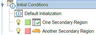
Region ID is an index used to denote different initialization items in the Workflow tree. As shown in Figure 3.26: Examples of initialization items under Initial Conditions, the first initialization item listed in the Workflow tree ("Default Initialization") receives region ID = 1, the second initialization item ("One Secondary Region") is given region ID = 2, the third item ("Another Secondary Region") is given region ID = 3, and so on.
Region ID is a spatially resolved variable (see Table 3.3: Spatially resolved variables that are eligible output to the solution file in Spatially Resolved Panel). You may use this variable to check the scope of the default initialization region and any secondary regions defined in the project.
Note: The Region ID should not be confused with the Initialization Order. They have different definitions.