


EnSight creates the following Boundary Layer Variables simultaneously on a 2D boundary part directly from velocity information of its corresponding 3D flow field part. Their corresponding variable names are included in all appropriate EnSight variable lists (Color Parts variable list and so on).
Important: The Boundary Layer Variables capability as well as all the Boundary Layer Calculator functions (BL_*) are not supported for Server of Server (SOS) decomposition because SOS was designed to benefit from independent Servers computations in parallel. The inter-dependent computational mapping of the field results from the fluid part onto the boundary part violates this assumption.
| Variable Name | Description | Symbol |
|---|---|---|
|
(N) bl_thickness |
Boundary layer thickness |
|
|
(N) bl_disp_thickness |
Displacement thickness |
|
|
(N) bl_momen_thickness |
Momentum thickness |
|
|
(N) bl_shape_parameter |
Shape parameter |
|
|
(N) bl_skin_friction_Cf |
Skin friction coefficient |
|


Only nodal (values per node) variables are created. Any dependent elemental variables (values per element) are averaged to nodal variables before processing. (See Definitions below.)
Whether these variables are mapped onto the 2D boundary part, or used in conjunction with other EnSight features (such as Elevated Surfaces of the boundary layer thickness off the 2D boundary part, Vortex Cores, Separation and Attachment Lines, Shock, etc.), these variables help provide valuable insight into the formation and location of possible boundary layers.
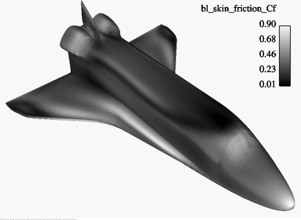
A boundary layer is a relatively thin region that confines viscous diffusion near the surface of a flow field, where the velocity gradient in the normal direction to the surface goes through an abrupt change. Although multiple boundary layers may be considered (especially in areas of flow separation), our current implementation provides boundary layer parameters based on the former concept. In these thin regions, the thickness of the boundary layer typically increases in the downstream direction, and the velocity parallel to the surface is much larger than the velocity normal to the surface.
Boundary parts are typically 2D surface part(s) that correspond to a 3D field. These surfaces may either be boundary parts defined directly from the data file, or created parts (for example, 2D IJK sweeps of a structured part, or an isosurface of zero velocity of either an unstructured or structured part).
Changes of the velocity in the normal direction from the surface into the 3D flow field are utilized to determine the boundary layer. EnSight automatically creates a velocity-magnitude gradient vector for all 3D model parts prior to creating the boundary layer variables. These gradient values are then mapped to all corresponding 2D model parts, and inherited by all created parts.
Note: The velocity-magnitude gradient vector variable will continue to be created for all 3D model parts until it is deactivated.
This vector variable behaves like any other created variable, and may be deactivated via the Feature Panel (Variables) dialog.
The following topics are included in this section:

The distance normal from the surface to where
 , where:

| magnitude of the velocity at a given location in the boundary layer |

| magnitude of the velocity just outside the boundary layer |
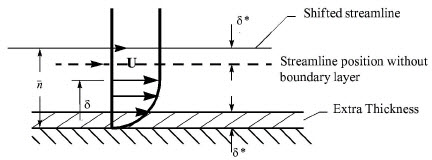

Provides a measure for the effect of the boundary layer on the outside flow. The boundary layer causes a displacement of the streamlines around the body.


Used to characterize boundary layer flows, especially to indicate potential for separation.
This parameter increases as a separation point is approached, and varies rapidly near a separation point.
Note: Separation has not been observed for H < 1.8, and definitely has been observed for H = 2.6; therefore, separation is considered in some analytical methods to occur in turbulent boundary layers for H = 2.0.
In a Blasius Laminar layer (flat plate boundary layer growth with zero pressure gradient), H = 2.605. Turbulent boundary layer, H ~= 1.4 to 1.5, with extreme variations ~= 1.2 to 2.5.

where:

| fluid shear stress at the wall. |

| dynamic viscosity of the fluid. May be spatially and/or temporarily varying quantity (usually a constant). |

| distance normal to the wall. |

| freestream density |

| freestream velocity magnitude. This is a non-dimensionalized measure of the fluid shear stress at the surface. An important aspects of the Skin Friction Coefficient is: |

| indicates boundary layer separation. |
Factor Determining Velocity at Boundary-Layer Thickness (δ).
The factor (default = 0.995) which determines the velocity magnitude (u) at the boundary-layer thickness (δ) with respect to the velocity magnitude (U) just outside the boundary layer (δ is the distance normal to the surface at which u = 0.995U), may be changed by issuing the following command via the command line processor Command Files):
test: blt_factor #
where # is the corresponding factor ( > 0.).
Refer to the following texts for more detailed explanations
P.M. Gerhart, R.J. Gross, & J.I. Hochstein, Fundamentals of
Fluid Mechanics, 2nd Ed., (Addison-Wesley: New York, 1992)
C.A.J. Fletcher, Computational Techniques for Fluid Dynamics,
Vol. 2, 2nd Ed., (Springer: New York, 1997)
Right-click any variable in the variables list and choose Boundary Layer Variables to create and update (make changes to) the boundary layer variables.
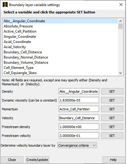
Opens the Boundary Layer Variable Settings dialog which allows you to identify and set the dependent variables used in computing the boundary layer variables (see Definitions above). This dialog has a list of current accessible variables to choose from. Immediately below is a list of dependent variables with corresponding text field and SET button. The variable name in the list is tied to a dependent variable below by first highlighting a the listed variable, and then clicking the corresponding dependent variable's SET button, which inserts the listed variable into its corresponding text field.
All text fields are required, except you may specify either Density and Momentum (which permits velocity to be computed on the fly), or Velocity. Default constant values are provided which may be changed by editing the text field.
Clicking OK activates all specified dependent variables and closes the dialog.
Freestream Density
Constant upstream density value (near flow inlet). Only used for skin-friction coefficient, Cf.
Freestream Velocity
Constant upstream velocity magnitude value (near flow inlet). Only used for skin-friction coefficient, Cf.
Opens a pop-up dialog for the specification of which type of method to determine the constant velocity just outside the boundary layer (U) (see Definitions above). The following options determine (U) at each node of the surface in the direction normal from the surface into the 3D field by:
Convergence Criteria
Monitoring the velocity profile until either the velocity magnitude goes constant or its gradient goes to zero.
Distance From Surface
Specifying the Normal Distance from the surface into the field at which to extract the velocity and assign as U. Then monitor the velocity profile from the surface into the field until U is obtained.
Normal Distance
Text field that contains the distance normal from the surface into the 3D field at which to extract the velocity for U.
Velocity Magnitude
Specifying the Velocity Magnitude to assign as U. Then monitor the velocity profile from the surface into the field until U is obtained.
Velocity Magnitude
Text field that contains the specified velocity magnitude to assign as U.
Note: Boundary Layer Variable feature extraction does not work with multiple cases.
| Problem | Probable Causes | Solutions |
|---|---|---|
|
Error creating boundary layer variables. |
Non-2D part selected in part list. |
Select only 2D parts. |
|
Undefined (colored by part color) regions on boundary surface. |
2D boundary surface node was not mapped to corresponding 3D field boundary node. |
Make sure corresponding 3D field part is defined. |