Usually, the only boundary condition that must be applied is a fixed support boundary condition on the build plate. This is described in step 1 in the procedural steps below.
If base unbolting and/or removal steps are included in your simulation, the fact that nonlinear stabilization is on by default should be enough to loosely hold parts in place to prevent rigid body motion when the base is removed. However, if you think you need additional constraints, consider using weak springs (first choice) or directly applying fixed boundary conditions on three nodes of the part (second choice) to prevent rigid body motion. These steps are described in Additional Constraint Options for Removal Steps.
Procedural Steps
To fix the bottom surface of the base plate, right-click the Static Structural object and then select Insert > Fixed Support. Select the bottom surface of the base plate (geometry selection) and hit Apply in the Details view. If you have a more detailed geometry for the base, such as one with bolt holes that you want to explicitly simulate, apply the boundary conditions to affix the plate accordingly.
Additional Constraint Options for Removal Steps
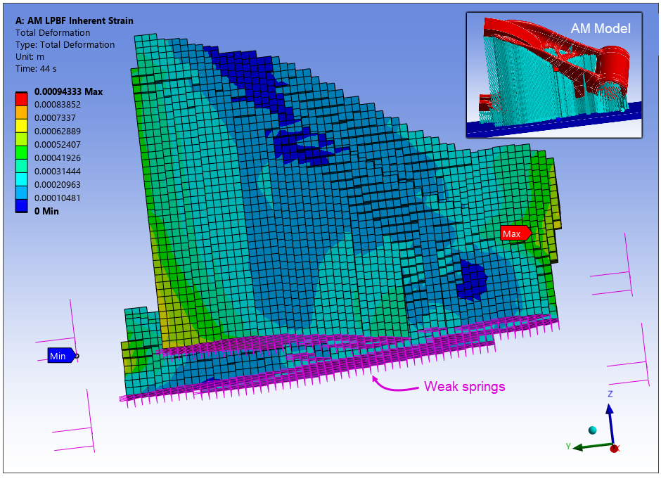
As a first option, insert a Weak Springs object into an LPBF Static Structural simulation to prevent rigid body motion when the default nonlinear stabilization is insufficient. In most cases, simulations should be able to reach convergence without this object, but it may be necessary on some occasions. When added, the object automatically scopes all nodes in the build at the interface of the parts/supports and the base. It attaches weak springs on the scoping (or a subset of the scoping) to hold the part in place without significantly affecting results.
To add weak springs, click the Weak Springs button in the LPBF Process ribbon. By default, nodes in the build geometries (part and support) at the interface with the base will be scoped to the weak springs object. Weak springs can also be scoped to the base or other non-build geometries. You should not scope build elements above the base to this object.
Weak springs are generated at the solve. To visualize where they are, before solving, do the following:
Under Analysis Settings in Solver Controls, set Weak Springs to On.
Under Static Structural > Solution, click Solution Information, and set Visible on Results to Yes in the FE Connection Visibility options.
After doing this, the weak springs should be visible when viewing result objects like Total Deformation.
Not every node scoped will get weak springs applied to it, it is dependent on how you set the Spring Creation setting. Each node that does get springs applied will have three springs, one in the x-direction, one in the y-direction, and one in the z-direction. You should ensure that the stiffness value is low enough that it is not affecting simulation results other than holding the parts in place. It is not recommended to scope weak springs above the interface of the build and base. Weak springs above that interface can affect the build process leading to incorrect results. You will see a warning if you have nodes or faces scoped above the build-base interface.
Three Nodes Option
In cases where both stabilization and weak springs are undesired for convergence, consider constraining the part at three nodes to prevent rigid body motion. Be aware that you will be constraining the nodes to their displaced position at the end of the build, rather than constraining them to 0. (For example, if the node displaced 0.1 mm during the simulation, the constraint will keep the node at 0.1 mm.) Use a Commands object to do this, as follows:
You may want to hide the base body during this process. Right-click the base body and select Hide Body.
Zoom in to the area of the part where you will apply constraints. Switch to Node mode of selection.
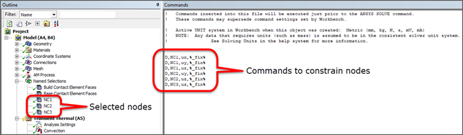
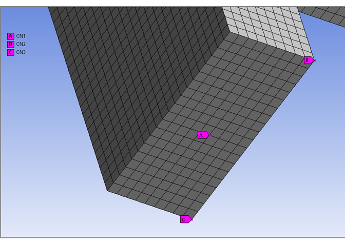
Create nodal named selections: Right-click Model in the project tree, and select Insert > Named Selection. Select a node on the bottom of the part, perhaps toward the middle of the part. You should choose nodes that are unimportant to your results. Perhaps spread them out over the bottom of the part but the nodes must not be co-linear. Your node selection will affect displacement results but not stresses or strains. Click Apply in Details. Right-click the newly created Selection in the project tree (under Named Selections) and select Rename. Name it to something short and descriptive, such as CN1 (for constrained node 1). Do the same step two more times and rename them to CN2 and CN3.
Create commands to constrain the nodes: Click the Static Structural object and select Commands
 from the context menu. Or, right-click
and select Insert > Commands. In the Commands window that is displayed, copy and paste, or type, the
following:
from the context menu. Or, right-click
and select Insert > Commands. In the Commands window that is displayed, copy and paste, or type, the
following:D,CN1,UX,%_FIX% D,CN1,UY,%_FIX% D,CN1,UZ,%_FIX% D,CN2,UY,%_FIX% D,CN2,UZ,%_FIX% D,CN3,UZ,%_FIX%
Constrained node 1 is fixed in UX, UY, and UZ and holds the part in place. Constrained node 2 is fixed in UY and UZ, and constrained node 3 is fixed in UZ; these prevent rotation. Selection of CN1 can have a big effect on the displacement throughout the part. See the D command, which defines degree-of-freedom constraints at nodes, for more information.
Match the commands to the base removal sequence step: Select the newly created Commands object under Static Structural and, in Details, change the Step Selection Mode to By Identifier. Change the Step Number to Removal Step: Base. This ensures the constraints are applied just before the base removal step.
Remember to make the base plate visible again if you hid the body. Right-click the base body and select Show Body.