8.12. Weak Springs

Loosely holds parts in place during AM postprocess steps to prevent rigid body motion.

Insert a Weak Springs object into an LPBF Static Structural simulation to prevent rigid body motion when the default nonlinear stabilization is insufficient. In most cases, simulations should be able to reach convergence without this object, but it may be necessary on some occasions. When added, the object automatically scopes all nodes at the bottom of the part and support geometries. It attaches weak springs on the scoping (or a subset of the scoping) to hold the part in place without significantly affecting results.
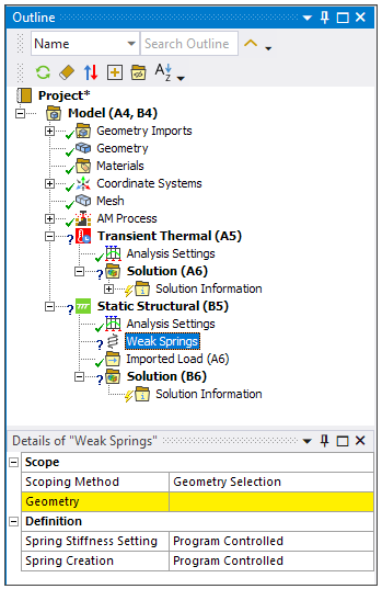
Object Properties

The Details Pane for this object includes the following properties.

CategoryProperties/Options/Descriptions

Scope

Scoping Method: Options include Geometry Selection (default) and Named Selections.

  • Geometry: Select either Faces or Mesh Nodes of the object. If the Grid option is chosen for Spring Creation the scoped nodes or faces need to be on a consistent Z-plane. When added, the object will automatically scope all nodes in the build geometries (part and support) at the interface with the base.

  • Named Selection: Select a Named Selection from the drop-down menu.

Definition

Spring Stiffness Setting: Choose Program Controlled, Factor, or Manual.

  • Program Controlled: Equivalent to using the Factor setting with a value of 1e-7.

  • Factor:

    • Spring Stiffness Factor: A factor used to indirectly specify the spring stiffness. Defaults to 1e-7. With this option, , where Area is the area represented by the scoped nodes, E is the elastic modulus, and Factor is the Spring Stiffness Factor.

      The area and elastic modulus in this equation are determined by Mechanical APDL whereas the Spring Stiffness Factor is user input. The elastic modulus is taken at either the room temperature specified in the AM Process object (for Thermal-Structural simulations), or the reference temperature of the body it’s associated with (for Inherent Strain simulations).

  • Manual:

    • Spring Stiffness: Stiffness value to be used by each spring.

Spring Creation: Choose Program Controlled, Grid, All Scoped Nodes, or All Scoped Corner Nodes.

  • Program Controlled: When scoped faces or nodes are all on the same Z-plane, the application uses the same as using the Grid option where the grid length is the total_element_volume/total_area where the area is the area associated with each scoped node and the volume is the element volume of elements associated with the scoped nodes.

    When scoped faces or nodes are not on the same Z-plane, the application defaults to All Scoped Corner Nodes.

  • Grid: When the Grid setting is selected, an X-Y grid of candidate points is created internally. For each point, the nearest corner node is identified, and if the node is within the Grid Spacing distance of the candidate grid point, weak springs are applied to it. This option is useful when a layered tetrahedral mesh is used, to provide a more uniform overall distance between weak springs when there may be smaller elements along part curves. The Grid option is only valid if the face or node scoping is in a consistent Z-plane.

    • Grid Spacing: Spacing used to identify weak spring locations.

  • All Scoped Nodes: Weak springs are placed on all scoped nodes or nodes associated with face scoping.

  • All Scoped Corner Nodes: Weak springs are placed on all scoped corner nodes or all corner nodes associated with scoped face(s). Corner nodes are those at the corners of an element (not the midside of an element edge).

Tree Dependencies

  • Valid Parent Tree Object: Static Structural

  • Valid Child Tree Objects: None.

Insertion Methods

  • Click the Weak Springs button in the LPBF Process ribbon.

  • Right-click Static Structural and then select Insert > Weak Springs.

Additional Related Information

Apply Structural Boundary Conditions