


Ansys Additive Suite™ is a powerful collection of tools from Ansys, Inc. dedicated to additive manufacturing simulation. This document describes the LPBF additive manufacturing simulation capabilities in the Ansys Mechanical™ application using the Ansys Workbench™ framework.
Target Users
Target users of AM capabilities in the Mechanical application are the engineers involved in the design and analysis of mechanical components, not necessarily manufacturing engineers and technicians tasked with printing the parts on the machine floor, nor the R&D researchers responsible for determining the ideal printing machine process parameters. Current users of the Ansys Discovery™ and Ansys Mechanical applications will benefit greatly from running AM Process Simulations if they plan to use additive manufacturing to print their metal parts.
Simulation Goals
The goal of Additive simulations in Mechanical is to predict the macro-level distortions and stresses in parts to prevent build failures and provide trend data for improving designs for additive manufacturing including part orientation and support placement and sizing.
The simulation is not meant to provide detailed thermal or structural results needed for prediction of micro-level process phenomena (that is, microstructure). The simulation will also not provide detailed guidance on the setting of the machine’s process parameters. Our complementary offerings of Ansys Additive Print and Additive Science (within Additive Suite) are the products to use to achieve those goals.
Methodology and Abstractions
Simulation of the manufacturing process requires that the analysis follows the build process itself: layer-by-layer solidification of the part. Since the thermal (temperatures) and structural (distortion and stress) physics are largely uncoupled (that is, a weak coupling), we can simulate the thermal phenomena first, layer-by-layer, and use those temperature results in a following structural simulation.
In an AM Process Simulation, the model evolves over time; that is, elements are added. We actually mesh the entire part first with a layered mesh (either Cartesian or Tetrahedrons) and then use the standard element birth and death technique to "turn on" element layers to simulate the build progressing. Additionally, the relevant boundary conditions also evolve such as thermal convection surfaces. The build step is complete when all the element layers have been added (made "alive").
The analysis times and time stepping are also driven by the process parameters and are not known a priori. These details are all handled internally during the solution.
Simulating the entire build process for a real part following the beam scan pattern would take enormous compute time making it impractical. To meet our goals in a reasonable compute time – meaning much less than the actual build time – we use the following abstractions:
Super layers: Actual metal powder deposit layers are aggregated into finite element "super layers" for simulation purposes. Since the temperature histories of each adjacent layer is similar, this lumping approach is appropriate. Note: The real machine build time is approximately the transient thermal build step simulation time multiplied by R^(1/3), where R is the number of deposit layers in one element super layer.
Layer-by-layer addition: Material is added and heated all at once for each element layer. For current generation machines and their scan patterns, this is a reasonable assumption. The in-plane thermal effects do not contribute to the distortion as much as the build direction thermal effects. This means we do not use scan pattern information as input.
Heat Application: Heat is applied to new layers in one of two ways, an applied temperature or power-based heat generation. For applied temperature, the assumption is that the process parameters for the build have been set appropriately so that (1) the developed temperature is always at or above melt (no lack of fusion) and (2) the developed temperature does not substantially exceed melt (no keyholing). For heat generation, the power input and absorptivity is specified and a heat generation load is applied to elements in the new layer. The time over which the heat generation is applied can be set to either a very quick "Flash" option where the energy is added in a short amount of time, or a longer "Scan Time" option where the energy is added over the amount of time it would take to scan the new element layer. In both timing options, the input energy is the same. More information on the heat generation option can be found in the command descriptions for the underlying Mechanical APDL™ commands AMBEAM and AMBUILD.
Time step size: Large integration time step sizes are used throughout the simulation. This is sufficient to capture the induced thermal and plastic strains driving the distortion. The localized smooth heating and cooling curves will not be captured in detail.
Supports: Supports are represented as an orthotropic homogenized solid. While you can provide detailed support geometry, modeling this way is sufficient to capture part distortion and obtain estimates of support failure.
Surrounding powder: For the powder bed process, the surrounding unmelted powder need not be explicitly modeled. Instead, the heat loss into the powder can be accounted for in a simplified approach using a convective boundary condition at the interface between powder and solid material.
The LPBF Process Add-on and the LPBF Setup Wizard
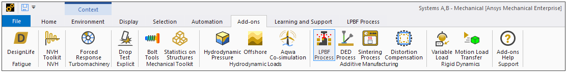
An AM process simulation can be run using native Mechanical interface objects and working through the project tree. For an easier approach, however, we recommend you load the LPBF Process Add-on, accessible from the Add-ons Tab in the Mechanical ribbon. Simply click the LPBF Process button (in the Additive Manufacturing group) to load the add-on. The button is shaded blue when the add-on is loaded.
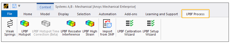
Click the LPBF Process tab to see the add-on's custom ribbon:
An easy-to-use LPBF Setup Wizard steps you through all the steps required to set up a simulation. If you are new to Ansys Workbench/Mechanical, or if you are an occasional user, we highly recommend you use the wizard. The workflow is described in Using the LPBF Setup Wizard. We also recommend you read Application Interface in the Mechanical User's Guide.
Even existing Ansys Workbench/Mechanical users may want to try the LPBF Setup Wizard because it's is an excellent tool for keeping you on track and preventing you from missing a task. There are a few advanced capabilities that are not available in the LPBF Setup Wizard, but because it does not include a solve, you can easily modify your simulation set-up after you complete the wizard. If you decide not to use the wizard, see Workflow Through the Project Tree for the procedure.
Elements, Commands, and Interface Objects Used in AM Process Simulations
The following tables show the primary elements, Mechanical APDL commands, and Mechanical interface objects used in AM Process Simulations. These items are well documented in our reference guides and links are provided.
| Element | Description |
|---|---|
| SOLID278 | 3D 8-node thermal solid element (Cartesian mesh) |
| SOLID185 | 3D 8-node structural solid element (Cartesian mesh) |
| SOLID291 | 3D 10-node tetrahedral thermal solid (Tetrahedrons mesh) |
| SOLID187 | 3D 10-node tetrahedral structural solid (Tetrahedrons mesh) |
| CONTA174 | 3D 8-node surface-to-surface contact element |
| TARGE170 | 3D target segment |
| SURF152 | 3D thermal surface effect |
| Command | Description |
|---|---|
| AMBEAM | For multiple-beam printers, specifies the number of beams. |
| AMBUILD | Specifies printer parameters for the build and other options. |
| AMENV | Specifies the build-environment thermal boundary conditions. |
| AMMAT | Specifies the build-material melting temperature. |
| AMPOWDER | Specifies the powder thermal conditions. |
| AMRESULT | Specifies AM-specific result data written to a .csv file. |
| AMSTEP | Specifies the process-sequence steps. |
| AMSUPPORTS | Specifies the information about supports. |
| AMTYPE | Specifies the printing process, PBF or DED. |
| Interface Object | Description |
|---|---|
| AM Bond | Establishes a connection between a meshed part and a meshed support in an AM Process Simulation. |
| AM Process | Identifies geometries and sets global options for all AM-related objects in an AM Process Simulation. |
| Build Settings | Defines strain assumptions, process parameters, and build conditions related to the additive machine, material, and process. |
| Generated Support | Creates a support structure consisting of finite elements. |
| LPBF High Strain | Identifies areas of high strain that are prone to cracking in an AM Process simulation. |
| LPBF Hotspot | Identifies areas of overheating that may result in problematic thermal conditions in an AM LPBF Thermal Structural simulation. |
| LPBF Hotspot Time Correction (Beta) | Identifies dwell times to correct overheating in an AM LPBF Thermal Structural simulation. |
| LPBF Recoater Interference | Identifies areas that may result in recoater interference issues in an AM Process simulation. |
| Predefined Support | Identifies a support structure that was imported with CAD geometry. |
| STL Support | Imports and meshes a support structure that is an STL (Stereolithography) file, of either volumeless or solid type. |
| Support Group | Groups Predefined Support objects and Generated Support objects. |
| Weak Springs | Loosely holds parts in place during AM post process steps to prevent rigid body motion. |
Known Issues and Limitations
Note the following limitations:
If you use a Mechanical Model from Workbench's Component Systems, you must manually create the AM Custom System. This is due to the fact that AM Custom Systems are pre-populated with AM sample materials in Engineering Data, and linking to the Mechanical Model necessitates the absence of materials in Engineering Data.
The LPBF Setup Wizard is not yet fully supported when using the standalone Mechanical application. For example, if you open the Mechanical application independent of Workbench and use the LPBF Setup Wizard to configure a heat treatment with creep properties, the creep properties will be incorrectly configured. Using creep properties from the wizard necessitates the use of Engineering Data in Workbench.
For a multi-part Inherent Strain simulation with either Scan Pattern or Thermal Strain strain definition and a generated scan pattern (rather than a build file), scan stripes will likely not align in the x-y direction between parts.
On machines with AMD processors, an Inherent Strain simulation with Thermal Strain strain definition fails by default. Workaround: Set a global environment variable of TF_ENABLE_ONEDNN_OPTS=0 and restart the Workbench/Mechanical application.
An Additive Manufacturing Process Simulation is not meant to be used in conjunction with any of these features: gasket elements, fracture, and remote boundary conditions.
When using Workbench scripting to open SpaceClaim and then use Additive Prep, the Additive tab may be missing and/or the tools in the Additive ribbon may be grayed out.
In certain configuration scenarios, and for some .scdoc geometries that were created prior to Release 2021 R2, if you have the Additive Prep license enabled in SpaceClaim you will not be able to open the Mechanical application from inside Ansys Workbench. Mechanical will begin to launch and then it gets stuck at this stage. If this happens, the workaround is to do one of the following:
Within SpaceClaim 2021 R2 or a subsequent release, save the older .scdoc geometry as a new file using Save, Save As, or Export from Additive Prep.
Clear the Additive Prep license check box in SpaceClaim, perform your work in Mechanical, and then go back into SpaceClaim to enable Additive Prep for your next session. Additive Prep license options are accessible in SpaceClaim by clicking File > SpaceClaim Options > License and then checking/unchecking Additive Prep.
Result items from the LPBF Process Add-on (LPBF Recoater Interference and LPBF High Strain) with an AM Octree simulation may cause the Mechanical application to crash if an analysis is cleared and resolved and then the result items are evaluated again.
Multiframe restarts are not supported for the build step. Restarts are supported for the other AM process steps.
Linux system:
The LPBF Setup Wizard introduced as the default wizard at Release 2023 R2 is not supported on a Linux platform. Linux users use the Legacy LPBF Setup Wizard instead, which is loaded as the default wizard on Linux systems.
The voxelized mesh option (Cartesian Mesh with Voxelization Option), one of the three recommended mesh methods for layered simulations, is not available on a Linux platform because the underlying voxelizer code is incompatible with Linux. Choose between a Cartesian mesh and a layered tetrahedrons mesh.
High Performance Computing
An AM Process Simulation can be very compute intensive. We recommend you use high performance computing using an Ansys HPC license to take advantage of more than four cores.