


As previously described, the following constraints are applied to both the thermal and structural analyses:
Additional boundary conditions and loads applied to the simulation are described below.
For the thermal model, two types of boundary conditions are used:
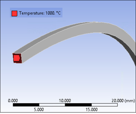
Constant temperature specified at the clamped end as illustrated in Figure 29.12: Constant Temperature Specified at Clamped End
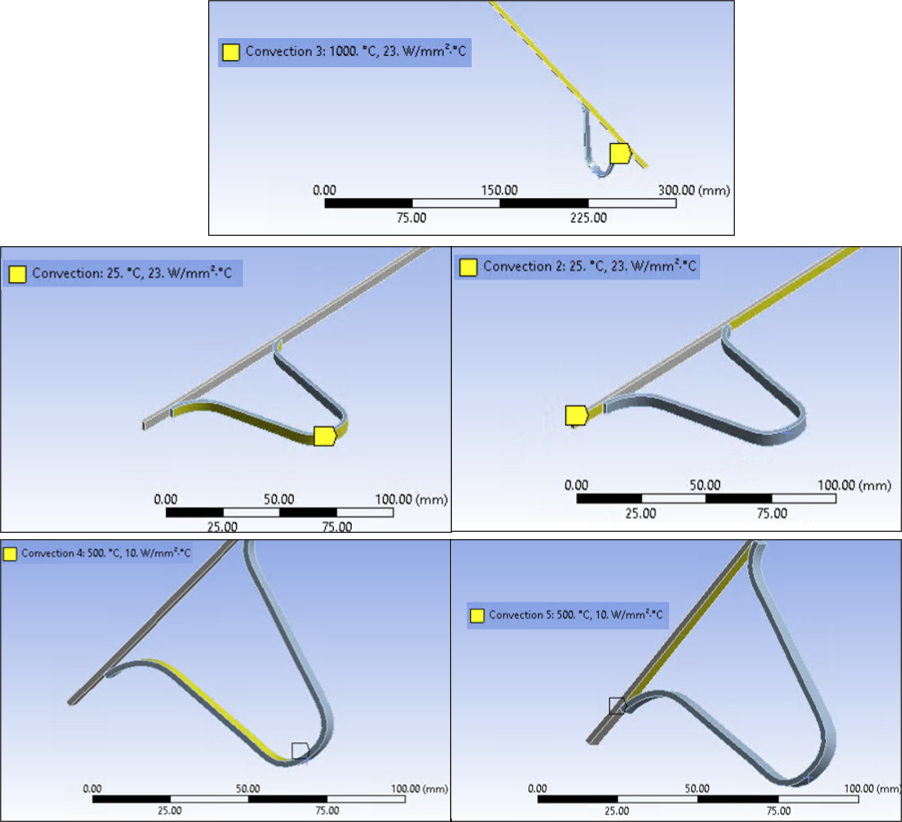
Three different film convection boundary conditions for different regions of the model as illustrated in Figure 29.13: Three Convection Boundary Conditions
A more realistic thermal model may have film coefficients that were derived from empirical correlations. Constant values are used here for simplicity. As an alternative, it is possible to specify heat flux boundary conditions instead of convection boundary conditions it is known a priori.
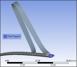
For the structural model, a fixed support is applied as shown below.
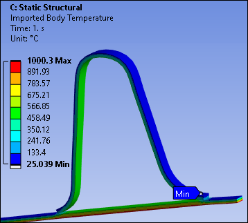
In addition, thermal loads are transferred to the structural model from the thermal model. This accomplishes loose coupling, as described in the introduction (see Figure 29.1: Project Schematic in Workbench) and shown in the screen shot below from the Mechanical Application.
For the structural analysis, other mechanical loads could be active that have been ignored, such as pressure and shearing stresses due to gaseous flows. A more realistic simulation would account for all possible loads that could be major contributors to stress.