


To reduce noise in an aircraft cabin, viscothermal quarter-wave resonator panels can be positioned within the cabin. Resonator tube lengths and diameters are optimized to maximize the sound absorption in the frequency range of interest. The resonator model studied here is typically tested using an impedance tube method. The following model replicated the impedance tube test setup with a back tube cavity. The back tube cavity is connected to several tubes of small diameter where viscothermal effects play an important role in the frequency response. The objective is to understand the sound absorption characteristics of the resonator through the absorption coefficient curves as a function of excitation frequency.
The following figure shows the geometry of the resonator model used in this simulation:
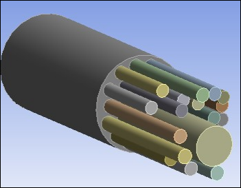
This figure shows the resonator is composed of tubes with variable diameters and lengths, resulting in an optimized absorption across the frequency range. The dimensions of the tubes are listed in Table 41.1: Tube Numbers, Radii, and Lengths.

Table 41.1: Tube Numbers, Radii, and Lengths
|
Tube Number |
Radius (mm) |
Length (mm) |
|---|---|---|
| 1 | 3.4 | 43.6 |
| 2 | 3.4 | 43.6 |
| 3 | 3.4 | 45.4 |
| 4 | 3.4 | 46.8 |
| 5 | 3.4 | 48.6 |
| 6 | 3.3 | 50.5 |
| 7 | 3.4 | 40.6 |
| 8 | 3.4 | 52.1 |
| 9 | 3.4 | 54.4 |
| 10 | 3.4 | 56.7 |
| 11 | 3.4 | 59.0 |
| 12 | 3.4 | 61.7 |
| 13 | 3.6 | 64.7 |
| 14 | 3.5 | 66.9 |
| 15 | 3.6 | 69.8 |
| 16 | 3.6 | 72.9 |
| 17 | 3.8 | 76.1 |
| 18 | 3.8 | 79.8 |
| 19 | 5.1 | 36.8 |
| 20 | 10.3 | 82.3 |