


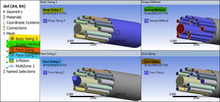
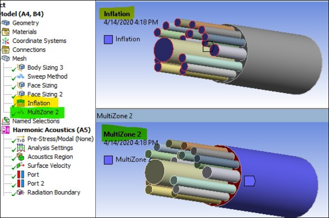
This example is solved using Ansys Workbench, and a workbench project archive (.wbpz) is available for download (see Input / Workbench Project Files). Once the geometry is imported, the model must be meshed using special consideration for acoustic solutions. The mesh controls highlighted in the images below have been added. The meshed model is used in this example problem to keep the mesh and results constant since results can be mesh sensitive. The element size chosen ensures at least six quadratic elements per wavelength for the highest frequency of interest. All bodies are grouped in a single part for node connectivity at the body's interfaces, i.e. shared (conformal) nodes across body interfaces resulting in perfect acoustic energy transfer across the interfaces. Note that mesh inflation is applied to the boundaries of the absorbing tubes to capture the boundary layers.
Two Harmonic Acoustics systems have been added to analyze and compare noise level reduction using two available viscothermal acoustic models, Boundary Layer Impedance (BLI) and Low Reduced Frequency (LRF) .
A normal velocity and a nonreflective radiation boundary are applied on the impedance tube inlet, simulating the sound generated experimentally by a speaker.
The Low Reduced Frequency (LRF) and Boundary Layer Impedance (BLI) models are applied on the resonator tubes in the first and second Harmonic Acoustics system, respectively, to analyze viscous and thermal effects. For more information on these acoustic models, see Viscous-Thermal Materials in the Acoustic Analysis Guide.