


The model uses PLANE182 2-D four-node structural solid elements with axisymmetric behavior (KEYOPT(3) = 1).
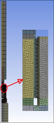
The mapped mesh for threads at critical locations are given an adequate mesh density.
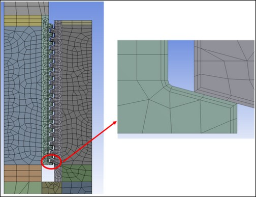
The 2-D axisymmetric model of the threaded connection has two contact pairs:
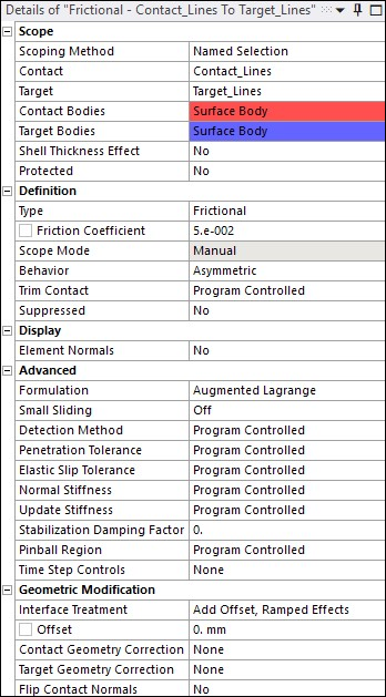
The flexible-to-flexible contact pair uses a low value of friction (µ= 0.05). A very small amount of initial penetration (included in the contact analysis) exists between threads. You can change some properties of this contact pair (such as including/excluding the initial penetration or modifying the pinball region) during the 2-D to 3-D mapping process. On rare occasions, some experimentation may be necessary to determine the contact parameters to resolve convergence issues if they arise during solution mapping (MAP2DTO3D,SOLVE). The figure below shows details of contact settings used for this contact.
The rigid-to-flexible contact pair plays no role in the 2-D axisymmetric analysis. It is required for the 3-D model, however, when applying the bending load on the extruded 3-D model via a pilot node created for this contact pair. This is defined using the following command snippet as below since it is not supported in Workbench Mechanical.
finish
/prep7
cmsel,s,Contact_Nodes
esln
esel,r,ename,,172
cm,Contact_Elements_New,element
allsel,all
cmsel,s,Total_Contact_Nodes
esln
esel,r,ename,,172
cm,New_Contact_Elements,element
allsel,all
*get,kpmax,kp,,num,max
*get,ymax,node,0,mxloc,y
nsel,s,loc,y,ymax
*get,xmax,node,0,mxloc,x
*get,xmin,node,0,mnloc,x
k,kpmax+1,xmin,ymax
k,kpmax+2,xmax,ymax
l,kpmax+1,kpmax+2
*get,etmax,etyp,,num,max
et,etmax+1,169
et,etmax+2,172
keyopt,etmax+1,2,1
keyopt,etmax+2,9,1
keyopt,etmax+2,12,5
nsel,s,loc,y,ymax
cm,tn.cnt,node
type,etmax+2
real,etmax+2
mat,etmax+2
esln
esurf
lsel,s,loc,y,ymax
lplot
type,etmax+1
lmesh,all
allsel,all

type,etmax+1
real,etmax+2
*get,nmax,node,,num,max
pilotnode=nmax+1
n,nmax+1,0,ymax
tshap,pilot
e,nmax+1
allsel,all
finish
/solu
When the 2-D axisymmetric mesh is extruded to the 3-D mesh (EEXTRUDE), the program creates both contact pairs for the 3-D model.