


The following topics are available:
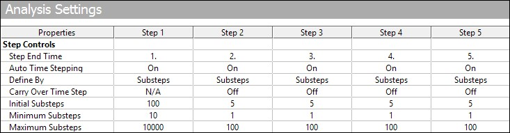
The analysis is non-linear with five load-steps. Auto Time Stepping is set On in each load-step to reduce the solution time. Analysis time step controls for the five time steps are specified as shown in the following figure.
The end-cap load is applied on the top end of the model using Nodal Pressure, and the bottom end is fixed in all degrees of freedom using Fixed Support as shown below.
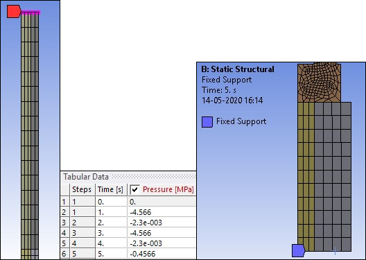
Internal Nodal Pressure is applied as illustrated in the following figure.
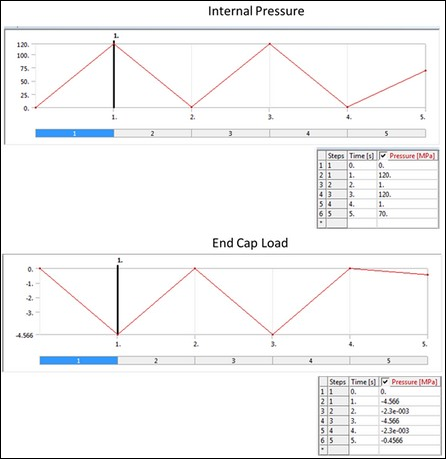
The internal pressure and end-cap loads are cycled as shown in the following plots.
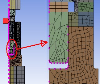
After converting the 2-D model to 3-D, a bending load is applied on the 3-D model. A rigid-to-flexible redundant contact pair was created in the 2-D model for this purpose. A bending load of 0.4 degrees is applied on the pilot node of the contact pair in the 3-D extruded model. This is done using command snippet as shown below as 2D to 3D extrude is not supported in Mechanical.
finish
/clear,nostart
/solu
antype,,restart,5,
allsel,all
time,6
d,pilotnode,all
d,pilotnode,rotz,-0.001745*4
nsub,50,1000,50
outres,all,all
rescontrol,,all,10
allsel,all
solve
finish