


Three models are prepared for this problem:
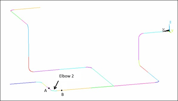
The entire piping system is examined in this model. Initially, a line diagram of the piping system is created:
The model type is set to Pipe for line bodies, and Pipe Idealization under Analysis Environment is used to model elbow elements.
Note: Ansys Workbench Mechanical supports pipes with eight cells around the circumference and general section deformation (the default value for ELBOW290 element with KEYOPT(2) = 2).
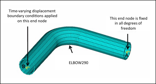
8.3.2. Local Elbow Model Meshed with ELBOW290 Elements
The local nonlinear analysis is focused on the elbow between locations labeled A and B in Figure 8.2: Entire Nuclear Piping System Line Diagram.
Following is the line diagram of this elbow model:
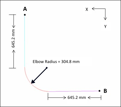
The model has branches that are 645.2 mm long and an elbow with a radius of 304.8 mm (for a total centerline length of 950 mm). The diameter of the pipe is 219.2 mm and the wall thickness is 10.38 mm. Pipe Idealization is used to model elbow elements.
Time-varying-displacement boundary conditions, extracted from a transient analysis of the entire piping system model under seismic loading, are applied at one end of the model. A nonlinear static analysis using the Chaboche material model is performed on this elbow model to obtain the stress and strain response over time.
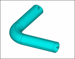
8.3.3. Local Elbow Model Meshed with SHELL281 Elements
An equivalent local 3-D model of the same elbow using SHELL281 elements is used to generate a reference solution. The 3-D surface representation of the elbow and the refined SHELL281 mesh are shown respectively in the following figures:

Material properties and loadings considered in this model are identical to those of the local ELBOW290 model. A conversion of boundary conditions from the global line mesh to the local 3-D shell mesh is necessary, however. Time varying displacement boundary conditions are applied to the pilot node at one end of the model. The pilot nodes are coupled with edge nodes at both ends via contact elements as shown in Figure 8.6: Elbow Model Meshed with SHELL281 Elements.