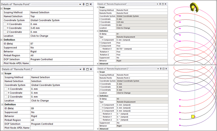
To apply boundary conditions, a Remote Point object is defined at each end of the tube/coil assembly. Each remote point ties together end nodes of the tube and the coil which are grouped into a Named Selection. (The solver uses multipoint constraint (MPC) equations to make these connections.) Then, Remote Displacement boundary conditions are defined at the remote points: the bottom end is fixed and the top end is rotated about the X direction by 1.2 radians.
The remote point and remote displacement settings for the three different cases are shown below. In each figure, the detail pane on the left shows remote point settings, while the detail pane on the right shows the corresponding remote displacement constraint on that remote point.
Case 1: At each end of the assembly, a named selection containing nodes on the tube and coil end faces is scoped to a remote point object.
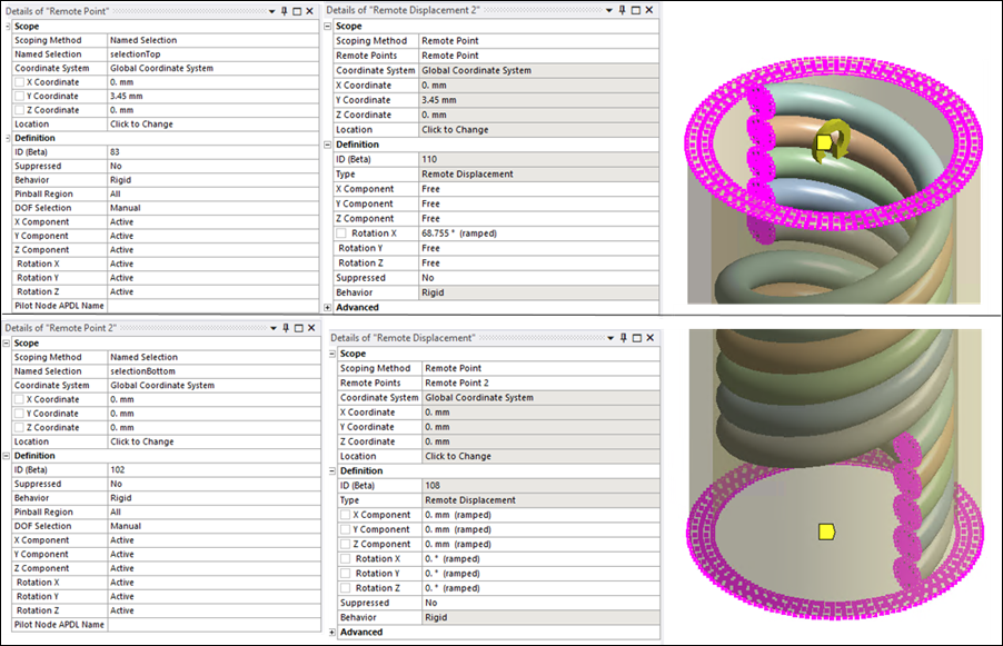
Case 2: At each end of the assembly, a named selection containing nodes on the tube end face and the coil end nodes is scoped to a remote point object.
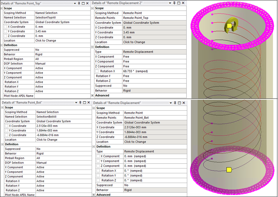
Case 3: At each end of the assembly, a named selection containing the tube end node and the coil end nodes is scoped to a remote point object.