Two models with surface flaws are considered for analysis:
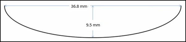
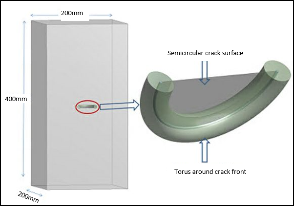
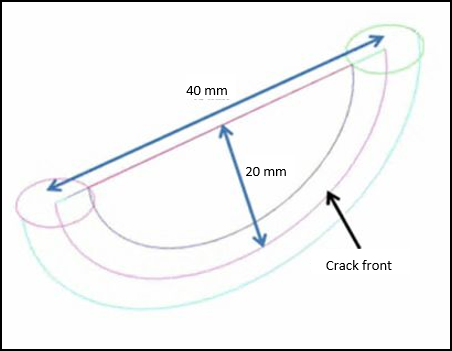
A Semi-Elliptical Crack object is used to simulate a semicircular surface flaw in a rectangular block. The block has a semicircular surface flaw with a 20 mm radius at the center of one longitudinal face of the rectangular block. The crack is perpendicular to the block's longitudinal surfaces and lies in the thickness direction as illustrated in Figure 16.1: Rectangular Block Geometry with Semicircular Surface Flaw. A torus is required around the crack front to control the mesh at the crack front.
The crack front and torus around the crack front are simulated with a Semi-Elliptical Crack object. This model is fixed at one face of the block and a pressure load is applied on the opposite face. The objective is to find SIFs (K1) and T-Stress along the crack front.
A semi-elliptical warped surface flaw at the tubular joint is simulated with a Pre-Meshed Crack object and an external mesh file to obtain mixed-mode SIFs (K1, K2 and K3) and T-Stress along the crack front.
The geometry consists of two tubular members (Tube 1 and Tube 2) attached to each other by a welded joint. The tubular members have outer diameters of 323.85 mm (D1), 219.08 mm (D2), and thicknesses of 15.88 mm (t1) and 8.18 mm (t2), respectively. The semi-elliptical surface crack lies on a plane parallel to the radial direction of the heavier running pipe as shown in the figure below.
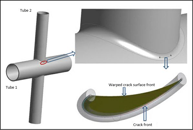
The semi-elliptical surface crack at the weld toe is warped along the welded joint, and it is perpendicular to the outer surface of the 323.85 mm diameter pipe in the thickness direction. Because of the two-plane symmetry inherent to the X-joint problem, a quarter model is analyzed. The crack front and torus around the crack front have already been specified in the external mesh file.