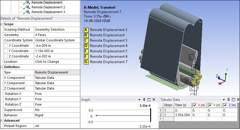
Remote Displacement with Rigid Behavior is applied to restrict movement in all directions for the rigid base of the punch assembly is constrained in all directions, as shown in the following figure.
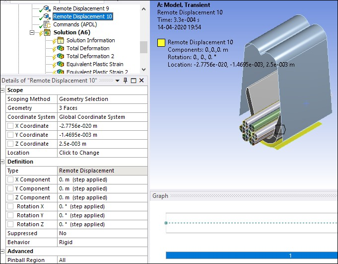
One end of each wire is constrained in all translation directions (but not rotations) and the other end of each wire is free. This is also accomplished using Remote Displacement with Rigid Behavior, as seen in the following figure.
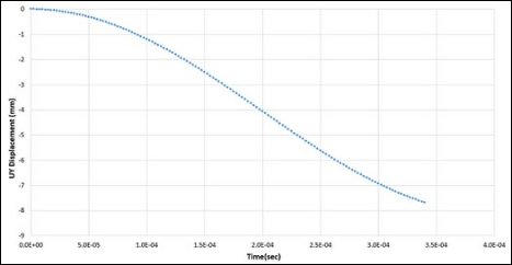
Finally, a Remote Displacement with Rigid Behavior is used to apply a downward displacement of 7.607 mm to the punch over 3.35 E-4 seconds. The time-varying displacement shown in Figure 42.9: UY Time Varying Remote Displacement is entered as tabular data. Displacements and rotations in other directions are constrained. (See Workbench Input Files and Project Files to download an excel file with the time varying downward displacement data.)