


This section describes the thermal and mechanical boundary conditions imposed on the FSW model:
The frictional and plastic heat generated during the FSW process propagates rapidly into remote regions of the plates. On the top and side surfaces of the workpiece, convection and radiation account for heat loss to the ambient [1]. Conduction losses also occur from the bottom surface of the workpiece to the backing plate.
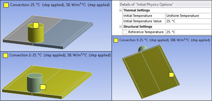
Available data suggest that the value of the convection coefficient lies between 10 and 30 W/m2 °C [1][2][3] for the workpiece surfaces, except for the bottom surface. The value of the convection coefficient is 30 W/m2°C for workpiece and tool. This coefficient affects the output temperature. A lower coefficient increases the output temperature of the model. A high overall heat-transfer coefficient (about 10 times the convective coefficient) of 300 W/m2 °C is assumed for the conductive heat loss through the bottom surface of the workpiece. As a result, the bottom surface of the workpiece is also treated as a convection surface for modeling conduction losses. Because the percentage of heat lost due to radiation is low, radiation heat losses are ignored. An initial temperature of 25 °C is applied on the model. Temperature boundary conditions are not imposed anywhere on the model.
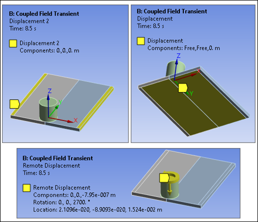
The workpiece is fixed by clamping each plate [1]. The clamped portions of the plates are constrained in all directions. To simulate support at the bottom of the plates, all bottom nodes of the workpiece are constrained in the perpendicular direction (z direction).
The FSW process consists of three primary phases:
Plunge -- The tool plunges slowly into the workpiece
Dwell -- Friction between the rotating tool and workpiece generates heat at the initial tool position until the workpiece temperature reaches the value required for the welding.
Traverse (or Traveling) -- The rotating tool moves along the weld line.
During the traverse phase, the temperature at the weld line region rises, but the maximum temperature values do not surpass the melting temperature of the workpiece material. As the temperature drops, a solid continuous joint appears between the two plates.
For illustrative purposes, each phase of the FSW process is considered a separate load step. A rigid surface constraint is already defined for applying loading on the tool.
The following table shows the details for each load step.
Table 28.3: Load Steps
| Load Step | Time Period (sec) | Loadings on Pilot Node | Boundary Condition | ||
|---|---|---|---|---|---|
| 1 | 1 | Displacement boundary condition |
| ||
| 2 | 7.5 | Rotational boundary condition |
| ||
| 3 | 22.5 | Displacement and rotational boundary conditions together on the pilot node |
|
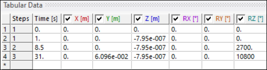
The tool plunges into the workpiece at a very shallow depth, then rotates to generate heat. The depth and rotating speeds are the critical parameters for the weld temperatures. The parameters are determined based on the experimental data of Zhu and Chao. The tool travels from one end of the welding line to the other at a speed of 2.7 mm/s.