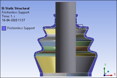
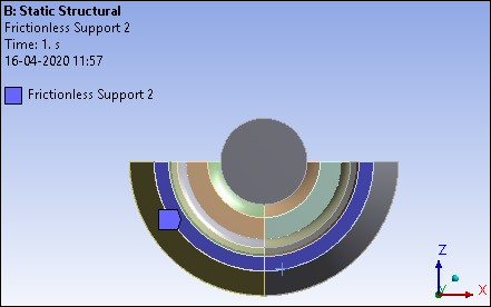
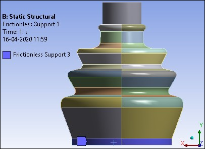
The model is constrained at the symmetry plane by restricting the out-of-plane translations. The bottom portion of the rubber boot is restricted in the axial and radial directions. This is done by applying Frictionless Supports as shown in the following figures.
Figure 26.12: Frictionless support at symmetry plane faces to restrict the out-of-plane translations
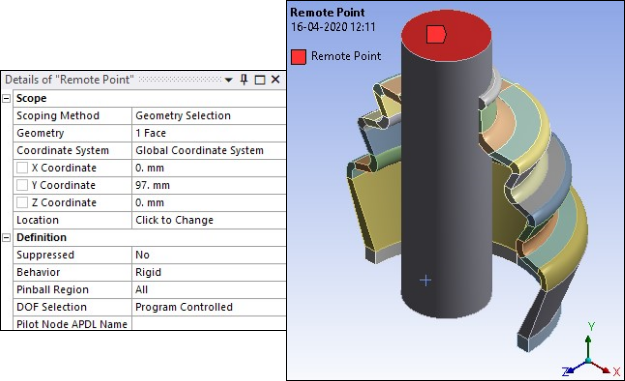
Remote Points are defined with RigidBehavior and are scoped to top and bottom faces of rigid shaft as shown in the following figures.
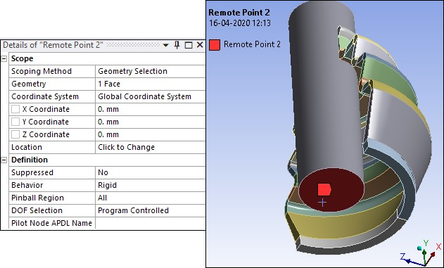
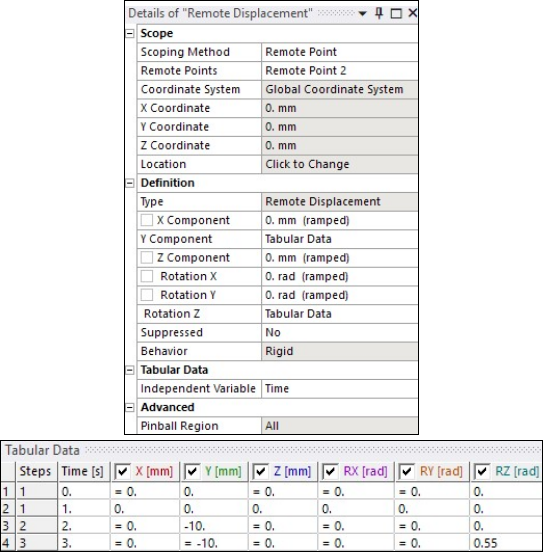
The Remote Displacement is applied in terms of displacements and rotations through different load steps scoped to the Remote Point at the bottom face of shaft (Remote Point 2 shown in the previous figure). The following load steps are specified:
Load step 1: Remote Displacement is constrained in all directions.
Load Step 2: Boot seal gets compressed when the shaft moves down. The vertical movement of the shaft is governed by the displacement applied to the base node (pilot node) at the end of the shaft's center axis. Downward displacement of 10 mm is applied.
Load Step 3: Shaft is rotated by giving rotation of 0.55 radians about z-axis to the base node (pilot node) at the end of the shaft's center axis.
The Remote Displacement is defined as shown in the figure below.