


VM-WB-MECH-113
VM-WB-MECH-113
Electro-Thermal Microactuator Analysis
Overview
|
Reference: |
Mankame, A. (2001). Comprehensive thermal modeling and characterization of an electro-thermal-compliant microactuator. Journal of Micromech, 252-262. |
|
Solver |
Ansys Mechanical |
|
Analysis Type(s): |
Coupled Field Static |
|
Element Type(s): |
3D Coupled Field Elements |
Test Case
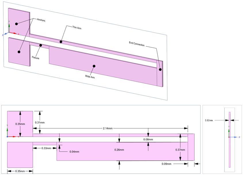
The actuator silicon structure has a thin arm connected to a wide arm, flexure, and two anchors as shown in the figure below. In addition to providing mechanical support, the anchors also serve as electrical and thermal connections. The actuator operates on the principle of differential thermal expansion between the thin and wide arms. When a voltage difference is applied to the anchors, current flows through the arms producing Joule heating. Because of the width difference, the thin arm of the microactuator has a higher electrical resistance than the wide arm, and therefore it heats up more than the wide arm. The non-uniform Joule heating produces a non-uniform thermal expansion, and actuator tip deflection.
Ansys Product Model
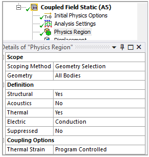
In Coupled Field Static for structural-thermoelectric conduction coupling, under the details of Physics Region, set the following definitions:
Structural: Yes
Thermal: Yes
Electric: Conduction
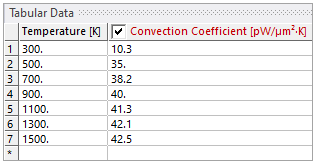
The boundary conditions details mentioned below consider the upper face as a front view of the electro-thermal microactuator of the sketch and the bottom face as a back view. The coefficient type used for all convection boundary conditions is the average film temperature except for thickness surface, where it is the surface temperature.
|
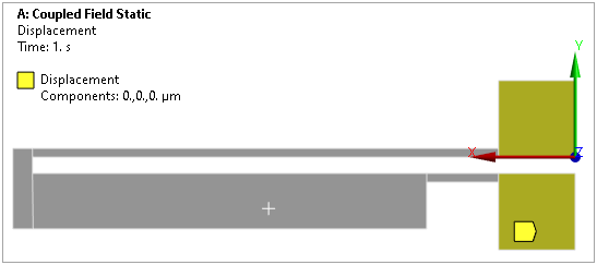
The Displacement is scoped to the bottom faces of the anchors. 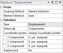 |
 |
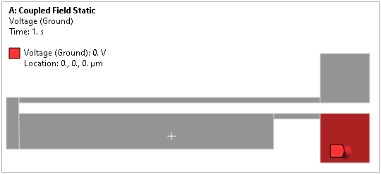
The Voltage (Ground) is scoped to the lower bottom face of the anchor. 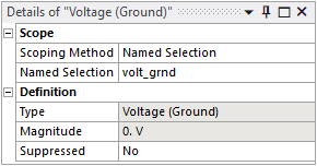 |
 |
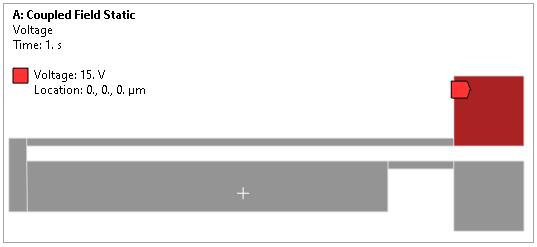
|
The Voltage is scoped to the upper bottom face of the anchor. 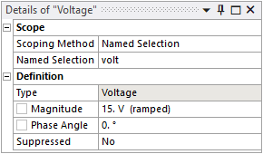 |
 |
|
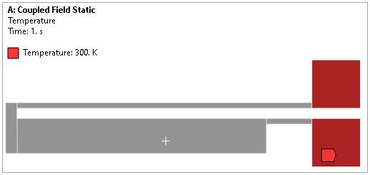
The Temperature is scoped to the bottom faces of the anchor.  |
 |
|
The Radiation is scoped to all exterior faces of the microactuator. 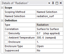 |
 |
|
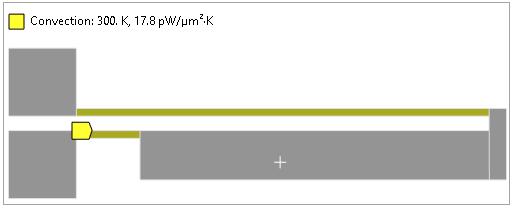
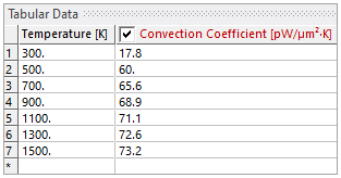
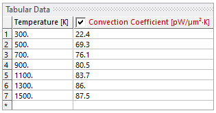
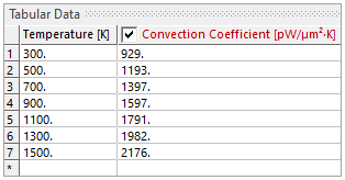
The Convection is scoped to the thin arm and flexure upper face.  |
  |
|
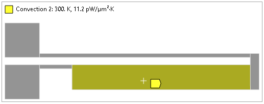
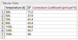
The Convection 2 is scoped to the wide arm upper face. 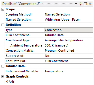 |
  |
|
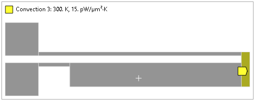
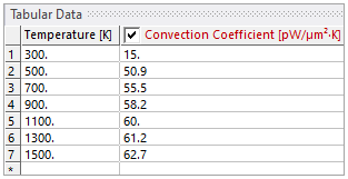
The Convection 3 is scoped to the end connection upper face. 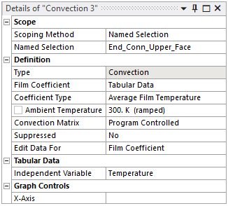 |
  |
|
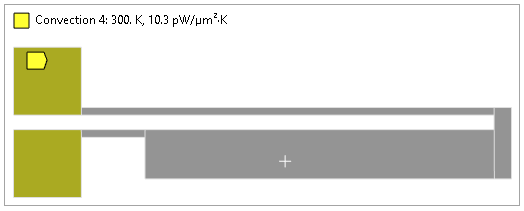
The Convection 4 is scoped to the upper faces of the anchors. 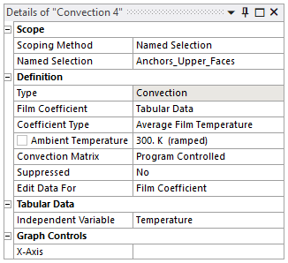 |
  |
|
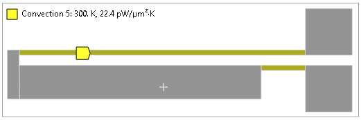
The Convection 5 is scoped to the thin arm and flexure bottom face. 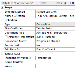 |
  |
|
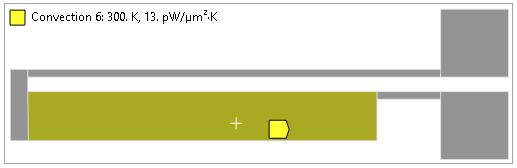
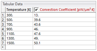
The Convection 6 is scoped to the wide arm bottom face. 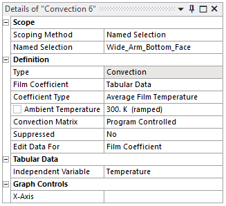 |
  |
|
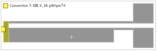
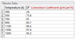
The Convection 7 is scoped to the end connections bottom face. 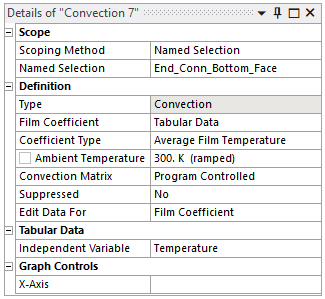 |
  |
|
The Convection 8 is scoped to the side wall faces of the microactuator excluding anchor faces and faces between the wide and thin arms. 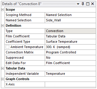 |
  |
Analysis Assumptions and Modeling Notes
A 3D static structural-thermoelectric analysis is performed to determine the tip deflection and temperature distribution in the microactuator when a 15 Volt difference is applied to the anchors. Radiative and convective surface heat transfers are also considered, which is important for accurate modeling of the actuator.
Ansys Product Modeling Notes
The finite element model uses a 3D 10-Node (Tetrahedral) Coupled-Field Solid (SOLID227).
Results Comparison for Ansys Product
The Workbench results are compared with experimental results specified in reference paper.
|
Directional Deformation Results (Y Axis) 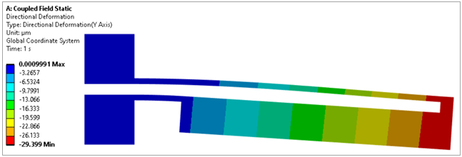 |
|
Temperature Results 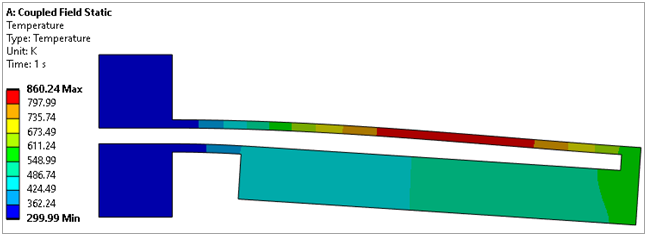 |
|
Electric Voltage Results 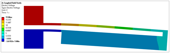 |
|
Joule Heat Results 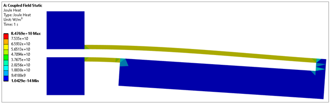 |
Results Table
| Target | Workbench App | Error (%) | |
| Tip Deflection in Y Direction (um) | -29.399 | -29.399 | 0.00% |