VM-WB-MECH-023

VM-WB-MECH-023
Curved Beam Assembly with Multiple Loads

Overview

Reference: Any basic Strength of Materials book
Solver(s):

Ansys Mechanical

Analysis Type(s): Linear Static Structural Analysis
Element Type(s): Beam

Test Case

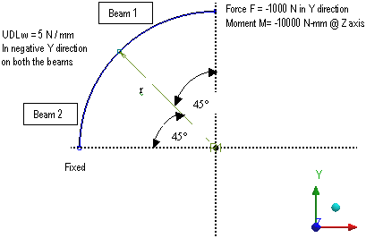
An assembly of two curved beams, each having an included angle of 45°, has a square cross-section. It is fixed at one end and at the free end a Force F and a Moment M are applied. Also, a UDL of "w " N / mm is applied on both the beams. Use a global element size of 30 mm to get accurate results. See the figure below for details.

Find the deformation of the free end in the y direction.

Figure 26: Schematic

Schematic

Equivalent Loading:

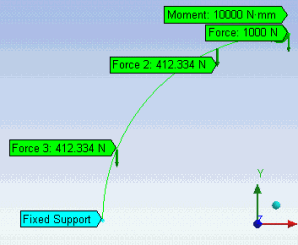
Schematic

Material PropertiesGeometric PropertiesLoading
Beam 1:
E1 = 1.1e5 MPa
ν1 = 0
ρ1 = 8.3e-6 kg/mm3
Beam 2:
E2 = 2e5 MPa
ν2 = 0
ρ2 = 7.85e-6 kg/mm3
For each beam:
Cross-section = 10 mm x 10 mm
Radius r = 105 mm
Included angle = 45°
Force F = -1000 N (y direction)
Moment M = -10000 Nmm (about z-axis)
UDL w = -5 N/mm (y direction) on both beams
This UDL is applied as an edge force on each beam with magnitude = -5 (2 x 3.14 x 105) / 8 = -412.334 N

Analysis

The deflection in the y direction is in the direction of the applied force F and is given by:

where:

δ = deflection at free end in the y direction
I = moment of inertia of the cross-section of both beams

Results Comparison

ResultsTargetMechanicalError (%)
Minimum Y Deformation (mm)-8.416664-8.46880.619