VM-EXD-MECH-002
VM-EXD-MECH-002
3-D Taylor Cylinder Impact
Overview
| Reference: | No theoretical solution. Experimental results and code-comparisons are available:
| ||
| Analysis Type(s): | Explicit Dynamics 3-D | ||
| Elements: | 8-Node Linear Interpolated Reduced Integration Hex | ||
| Boundary Conditions: | Fixed Constraint | ||
| Structural Interactions: | Trajectory Contact | ||
| Fluid-Structure Interactions: | No | ||
| Bonds: | No | ||
| Materials: | Copper |
Test Case
The Taylor cylinder impact test uses a right circular cylinder of a test material which impacts a theoretically rigid target. In this test, an OHFC copper cylinder, 0.762 cm in diameter and 2.54 cm in length, impacts a rigid plate at 19000 cm/s.
| Material Properties | Geometric Properties | Loading | ||
|---|---|---|---|---|
| Cylinder material = copper |
| Impact velocity = 190 m/s |
Analysis Assumptions and Modeling Notes
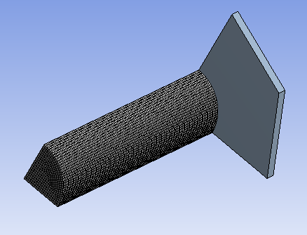
Two parts are created to model the copper cylinder and the rigid plate. Quarter symmetry is used to reduce simulation time.
Material data for copper is obtained from the Explicit Materials data source in Engineering Data. This data is the same as the material data used in the code comparison reference.
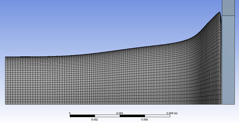
A 0.2 mm element size is used to mesh the cylinder. The rigid plate is modeled with a single element.
Trajectory contact is used to compute the impact of the cylinder on the plate. The initial velocity of the cylinder is 190 m/s and the simulation is run for 8 x 10⁻⁵ s.
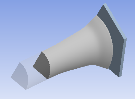
Results Comparison
The final cylinder profile is similar to the profile for the rigid body dynamics results (shown in the code-comparison reference). The cylinder radius in the impact plane agrees well with the experimentally obtained values, as well as with other simulation programs. The final cylindar length in this simulation is greater than the experimental value, but agrees well with the length computed by the other simulation programs using the same material model for copper. The plot below shows the final share of the deformed copper cylinder at the end of the simulation, compared to the original shape (semi-transparent).