


The Mechanical application enables you to apply temperatures from a thermal analysis as loads in a structural analysis for thermal stress evaluations. The load transfer is applicable for cases when the thermal and structural analyses share the mesh as well as for cases when the two analyses are solved using different meshes. For cases when the meshes are different, the temperature values are mapped and interpolated between the source and target meshes.
Workflow for performing a thermal stress analysis with:
- Shared Model
From the toolbox, drag and drop a transient or steady-state thermal template onto the project schematic. Perform all steps to set up a Steady-State Thermal or Transient Thermal. Specify mesh controls, boundary conditions, and solution settings as you normally would and solve the analysis.
Drag and drop a Static Structural, Transient Structural or LS-DYNA template on top of the thermal system's solution cell to enable the data transfer.
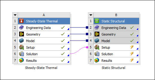
Double-click the structural systems Setup cell. In the Mechanical application an Imported Body Temperature load is automatically added into the structural system's tree under an Imported Load folder.
Select appropriate geometry in the Details view of the Imported Body Temperature object using the Geometry or Named Selection scoping option. If the load is scoped to one or more surface bodies, the Shell Face option in the details view enables you to apply the temperatures to Both faces, to the Top face(s) only, or to the Bottom face(s) only. See Imported Body Temperature for additional information.
Note: In a LS-DYNA system, temperatures cannot be scoped to beams.
Change any of the columns in the Data View tab as needed:
Source Time: The time at which the data will be imported from the thermal analysis.
Analysis Time: Select the analysis time at which the load will be applied.
Note: The Data View can automatically be populated with the source and analysis times using Source Time property in the Details view. Use All to import data at all times in the source analysis, or Range to import data for a range specified by a Minimum and a Maximum.
Right-click the Imported Body Temperature object and click Import Load to import the load. When the load has been imported successfully, a contour plot of the temperatures will be displayed in the Geometry window.
Note: The range of data displayed in the graphics window can be controlled using the Legend controls options. See Imported Boundary Conditions for additional information.
You can define multiple rows in the Data View tab to import source data at multiple times and apply them at different analysis. If multiple rows are defined in the Data View, it is possible to preview imported load vectors/contour applied to a given row or analysis time in the Data View. Choose Active Row or Analysis Time using the By property under Graphics Controls in the details of the imported load and then specify the Active Row/Analysis Time to preview the data.
Note: If the Analysis Time specified by the user does not match the list of analysis times in the Data View, the data is displayed at the analysis time closest to the specified time.
- Unshared Model
From the toolbox, drag and drop a steady-state or transient thermal template onto the project schematic. Perform all steps to set up a Steady-State Thermal or Transient Thermal. Specify mesh controls, boundary conditions, and solution settings as you normally would and solve the analysis.
Drag and drop a Static Structural, Transient Structural or LS-DYNA template onto the project schematic. Share the Engineering Data and Geometry cells if required and then drag the Solution cell of the thermal system onto the Setup cell of the structural system.

Double-click the structural systems Setup cell. In the Mechanical application, an Imported Body Temperature load is automatically added into the structural system's tree under an Imported Load folder.
Select appropriate geometry in the Details view of the Imported Body Temperature object using the Geometry or Named Selection scoping option. If the load is scoped to one or more surface bodies, the Shell Face option in the details view enables you to apply the temperatures to Both faces, to the Top face(s) only, or to the Bottom face(s) only. See Imported Body Temperature for additional information.
Note: In a 3D analysis, if the Triangulation mapping algorithm is used, the Transfer Type mapping option defaults to Surface when the load is scoped to shell bodies.
Note: In a LS-DYNA system, temperatures cannot be scoped to beams.
The Source Bodies option in the Details view enables you to select the bodies, from the thermal analysis, that make up the source mesh for mapping the data. You can select one of the following options:
Automatic: The application uses heuristics based on the geometry to automatically match source and target bodies and map temperature values. A source body is matched with a target body if it satisfies the following criteria:
The percent volume difference is within the user-defined tolerance.
The distance between the centroid locations divided by the diagonal of the bounding box is within the user defined tolerance.
The percent tolerance values can be specified in the Tolerance field. The default is set at 1%. The matching process is done in increments of 0.1 of the tolerance value, up to the defined tolerance. The process fails if multiple source bodies are found to match a target body or if no match is found for a target body. After the import is completed, a Load Transfer Summary is displayed as a comment object in the particular load branch. The summary shows the matched source and target bodies as well as the values that were used to determine the match. It is recommended that you verify the import using this information.
Important: This option requires that:
Element volume results are present in the thermal results file. In the thermal analysis, make sure that the Calculate Thermal Flux or the General Miscellaneous property under the Analysis Settings object is set to Yes so that this result is available.
Each scoped body of the target has a matching source body with a unique material id. Therefore, this option may not work when Imported Trace or Material Assignment objects are present.
Note: This option is not allowed when scoped to a node-based Named Selection as the heuristic is geometry based.
All: The source mesh in this case will comprise all the bodies that were used in thermal analysis. For cases where the temperature values are significantly different at the boundaries across two or more bodies, this option could result in mapped target values that are generated by taking a weighted average of the source values across multiple bodies. Target regions can exist where the mapped temperatures differ significantly from the source.
Manual: This option enables you to select one or more source bodies to make up the source mesh. The source body selections are made in the Material IDs field by entering the material IDs that correspond to the source bodies that you would like to use. Type material IDs and/or material ID ranges separated by commas to specify your selection. For example, type 1, 2, 5-10. The material IDs for the source bodies can be seen in Solution Information Object of the source analysis. In the example below, text is taken from a solver output,
***********Elements for Body 1 "coil" ***********
***********Elements for Body 2 "core" ***********
***********Elements for Body 3 "bar" ************
body 'coil' has material ID 1, body 'core' has material ID 2 and body 'bar' has material ID 3.
Change any of the columns in the Data View tab as needed:
Source Time: The time at which the data will be imported from the source analysis.
Analysis time: Choose the analysis time at which the load will be applied.
Note: The Data View can automatically be populated with the source and analysis times using Source Time property in the Details view. Use All to import data at all times in the source analysis, or Range to import data for a range specified by a Minimum and a Maximum.
You can transform the source mesh used in the mapping process by using the Rigid Transformation properties. This option is useful if the source geometry was defined with respect to a coordinate system that is not aligned with the target geometry system.
You can modify the Mapper Settings to achieve the desired mapping accuracy. Mapping can be validated by using Mapping Validation objects.
Right-click the Imported Body Temperature object and click Import Load to import the load. When the load has been imported successfully, a contour plot of the temperatures will be displayed in the Geometry window.
You can define multiple rows in the Data View tab to import source data at multiple times and apply them at different analysis. If multiple rows are defined in the Data View, it is possible to preview imported load vectors/contour applied to a given row or analysis time in the Data View. Choose Active Row or Analysis Time using the By property under Graphics Controls in the details of the imported load and then specify the Active Row/Analysis Time to preview the data.
Note: If the Analysis Time specified by the user does not match the list of analysis times in the Data View, the data is displayed at the analysis time closest to the specified time.
Note:You can add a template for the linked thermal and structural systems by creating your own template.
The transfer of temperatures is not allowed between a 2D analysis and 3D analysis or vice-versa.
Note: If the upstream (thermal) system is modified and re-solved after importing the load, a refresh operation on the structural system's Setup cell is required to notify Mechanical that source data has changed and re-import is required. Alternatively, the source data can be refreshed using the Right-click operation on the Imported Load folder and choosing the Refresh Imported Load option.
Note: When there is a shared model that includes a thermal-stress analysis and the structural system is duplicated using the Engineering Data, Geometry or Model cell context menu, the result is the Setup cell of the Thermal system linked to the Solution cell of the duplicated structural system. Temperature transfer to the duplicated structural system will require the data to be mapped and interpolated between the source and target meshes.