


Computation of Friction Force and Torque
The forces and moments that are used to evaluate the frictional effects are taken at the beginning of the time step. The resisting force and torques have a sign that is opposed to that of the velocity which is also evaluated at the beginning of the time step. In other words, the friction force and torque, during a given time step, are evaluated with the forces and torques of the previous time step and have the opposite sign of the velocity evaluated at the previous time step.
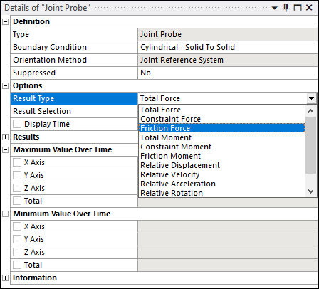
Postprocessing Joint Friction
For translational, revolute, cylindrical, point on curve, spherical, slot, universal and general joints, the Joint Probe allows you to verify the friction force and the friction moment. Friction force is available for translational, cylindrical, point on curve, slot, general, and all imperfect joints. Friction moment is available for revolute, cylindrical, point on curve with free rotations, spherical, slot, universal, general, and all imperfect joints.
Note: Joint Friction is only supported by the Ansys Rigid Dynamics Solver.
Setting Joint Friction With a Command
The command SetFrictionVariable(
replaces the constant value already given to the friction coefficient with the expression
given by var)var.
For example, to set 
Example 9.3: Setting Variable Joint Friction
Joint = CS_Joint.Find(_jid)
Var = CS_Variable()
u0 = 0.1
u1 = 0.2
alpha = 0.5
Var.SetFunc('u0+u1*exp(-alpha*time)',0)
Var.AddInputMeasure(Joint.GetVelocityMeasure())
Joint.SetFrictionVariable(Var)
The command has no effect if no value for the friction coefficient has been provided in the UI.
Setting the Friction Tolerance
The command
SetFrictionTolerance( sets the
friction tolerance.tol)
Example 9.4: Setting Friction Tolerance
Joint = CS_Joint.Find(_jid)
Joint = Joint.SetFrictionTolerance(1e-4)
Setting the Static Friction Coefficient with a Command
The static friction coefficient is by default set to the dynamic friction coefficient. The command SetStaticFrictionCoefficient(muS) changes its value to muS.
Example 9.5: Setting the Static Friction Coefficient
Joint = CS_Joint.Find(_jid)
Joint.SetStaticFrictionCoefficient(0.2)
Bending Moment for Translational Joints
When using a non-zero length when defining the friction in a joint, the bending
effect is proportional to the constraint moment existing in the joint. This moment is
always defined as the moment expressed at the reference coordinate system of the joint.
For joints that have translational degrees of freedom, such as the translational or
cylindrical joint, the reference coordinate system and mobile coordinate system are not
always at the same location, and the constraint force  generates a moment at the reference coordinate system:

In this example, the blue mass slides on a fixed red bar, under vertical gravity.
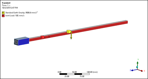
As the mass moves to the right the reported moment at the reference coordinate system, which stays at the end of the blue bar, increases linearly.
If a length has been specified in the translational joint, the friction bending forces will increase with the position. In this example, this is not the expected effect.
However, if the blue mass is grounded and the red bar is sliding in it, the moment reported in the reference coordinate system is also increasing and so should the friction bending forces.
You must choose the reference and mobile coordinate systems and effective length properly to represent the physics, as the "joint" abstraction can be sometimes misleading.
Note: This does not apply to the point on curve joint, as this joint uses an intermediate
coordinate system called a floating reference coordinate system,
which is always coincident with the mobile coordinate system. This floating reference is
used to measure the torque, therefore the vector  is always zero.