


Contact conditions are formed where rigid bodies meet. While the default contact settings and automatic detection capabilities are often sufficient for structural analyses, the default contact definition must be extended to adjacent surfaces in some cases. This is because the nature of rigid dynamics usually implies very large displacements and rotations.
In rigid dynamics, supported contact types depend on where the contact is defined and which time integration type is used:
Frictionless and forced frictional contact are available for all time integration schemes.
Rough contact and no separation contact are supported by the Runge-Kutta, Generalized-Alpha, and Stabilized Generalized-Alpha time integration schemes.
Bonded contact is only supported within condensed parts.
The contact is always based on Pure Lagrange formulation. Contact constraint equations are updated at each time step, and added to the system matrix through additional forces of degrees of freedom called Lagrange Multipliers. In this formulation, there is no contact stiffness. Contact constraints are satisfied when the bodies are touching, and they are nonexistent when bodies are separated.
- Contact and Rigid Bodies
Contact is formulated between rigid bodies. Hence, there is no possibility of deforming the bodies to satisfy the contact constraint equations. If the contact equations cannot eventually be satisfied, the solution will not proceed. To illustrate this, two examples are considered:
Example 9.1: Cylindrical Shaft in a Block
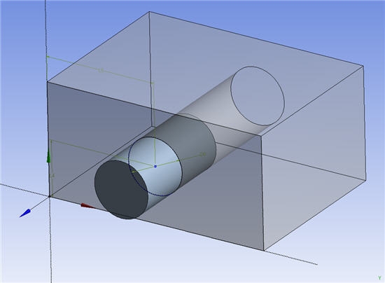
If the diameter of the cylindrical shaft is smaller than that of the hole, motion is possible.
If the diameter of the cylindrical shaft is larger than that of the hole, the simulation is not possible.
If the two diameters are exactly equal, then the analysis might fail.
Example 9.2: Block Sliding on Two Blocks
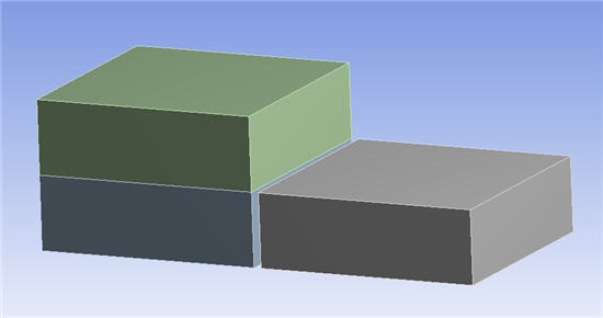
If the green block slides horizontally from left to right and the height of the right block is less than that of the left block, motion is possible.
If the height of the two bottom blocks is identical and a vertical contact surface is defined between the two bottom blocks, the block might hit the vertical surface, and the solution will not proceed.
If the height of the right block is greater than the height of the left block, the green block will move back to the left.
Note: Avoid ambiguous configurations whenever possible. Consider creating fillets on sharp edges as a workaround.
- Contact Mesh
You can scope the contact objects to rigid bodies using 3-D faces in solid bodies, or pick the entire body. When you create this type of contact, the surfaces and edges in the contact region are meshed.
The mesh is used differently depending on the RBD Contact Detection setting:
When RBD Contact Detection is set to Geometry-Based, the mesh helps to speed up the solution by providing an initial position to the contact points that are calculated, and it helps to drive the number of contact points used between the bodies when in contact. As each body has up to 6 degrees of freedom, a contact between two rigid bodies will restrain up to 6 relative degrees of freedom. This means that a reasonably coarse mesh is generally sufficient to define the contact surface. The contact solver will use this mesh to initiate the contact geometry calculation, but will then project back the contact points to CAD geometry. Refining the mesh can increase the solution time without always increasing the quality of the solution. Conversely, refining the mesh can be useful if the geometry is concave and the solver reports a high amount of shocks for the pair involving the concave surfaces.
When RBD Contact Detection is set to Mesh-Based, contact points are on the mesh, while the contact normal is still evaluated on the geometry. In conjunction with the Moreau-Jean time integration type, mesh-based contact detection can handle more refined meshes that capture smaller geometry details.
- Contact and Time Step
The rigid solver uses event-based time integration. Over each time step, the solver evaluates the trajectory of the bodies, and checks when these trajectories interfere. When interference is found (as with stops on joints), a shock will be analyzed, leading to a new velocity distribution. The physics of the velocity redistribution during the shock is based on the conservation of momentum and energy. The amount of energy lost during the shock is quantified by the coefficient of restitution. For details, see Joint Stops and Locks. The trajectory detection of interferences allows the use of rather large time steps without missing the contacts; however, transitions between adjacent contact surfaces in certain situations (such as sliding situations) often require smaller time steps.
In contrast to Penalty based simulation that introduces an artificial deformation of the bodies and therefore, high frequencies in the simulation, the pure Lagrange formulation used in the rigid dynamics formulation does not change the frequency content of the simulation.
A solution that includes contact requires an increased amount of geometrical calculation, resulting in a significantly higher overall simulation time than a solution without contact. As such, it is recommended that joints stops are used in place of contacts whenever possible.
- Limitations
For models with sliding contacts (such as cams, guiding grooves, and so on), small bounces due to nonzero restitution factors can cause an increase in simulation time and instabilities. Using a restitution factor of zero will significantly speed up the simulation.
The Rigid Dynamics solver unifies contact regions defined between the same pairs of parts/bodies. Consequently, defining more than one contact region between the same pairs of bodies may lead to unpredictable results. The following guidelines are strongly recommended:
All contact regions defined between the same pairs of parts/bodies must have the same type. Mixing different types (for example, frictionless and rough) may lead to incorrect results.
All contact regions defined between the same pairs of parts/bodies must follow the same order. A body defined as a target body in one contact region must not be defined as contact body in another contact region between the same pairs of parts/bodies.