


This example considers the gear mechanism shown below.
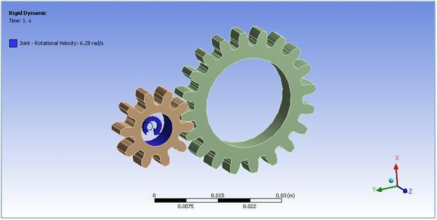
A relation is created between two revolute joints to simulate a gear with a ratio 2 M. Commands are used to enforce the ratio of velocities between the two wheels, and create a linear relation between rotational velocities, defined by:
(1)*ω 1 + (-2)*ω2 = 0
First, the joint objects are retrieved using their IDs:
j1id = CS_Joint.Find(_jid)
j2id = CS_Joint.Find(_jid)
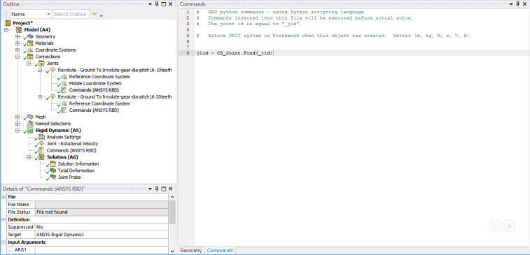
Next, the relationship between the two wheels is defined. The complete list of commands is shown below. A description of these commands follows.
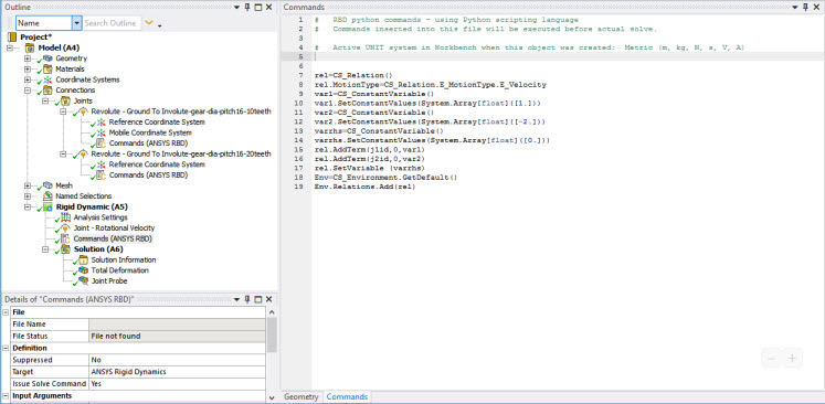
A relation object is created and specified as a relation between velocities:
rel=CS_Relation()
rel.MotionType=CS_Relation.E_MotionType.E_Velocity
The constant coefficients that appear in the relation are created. The first constant term is created by:
var1=CS_ConstantVariable()
var1.SetConstantValues(System.Array[float]([1.]))
The second coefficient and constant right hand side are created by:
var2=CS_ConstantVariable()
var2.SetConstantValues(System.Array[float]([-2.]))
varrhs=CS_ConstantVariable()
varrhs.SetConstantValues(System.Array[float]([0.]))
The first term of relation (1) X ω_1 is added to the relation object:
rel.AddTerm(j1id,0,var1)
The first argument is the joint object. The second argument defines the DOF (degrees of freedom) of the joint that are involved in the relation. Here,
0represents the rotation, which is the joint’s first and only DOF is the rotation.The second term and right hand side are introduced in the same manner:
rel.AddTerm(j2id,0,var2)
rel.SetVariable (varrhs)
The relation is added to the list of relations:
Env=CS_Environment.GetDefault()
Env.Relations.Add(rel)