There are four types of Direction:
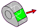
Planar Face

 Selected planar face. The load is directed normal to the face.
Note: Not applicable to Rotational Velocity or Rotational Acceleration. These objects are aligned along the normal to a planar face and along the axis of a cylindrical face.
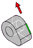
Edge
- Straight
Colinear to the edge
- Circular or Elliptical
Normal to the plane containing the edge


 Selected straight edge
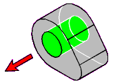
Cylindrical Face or Geometric Axis
Applies to cylinders, cones, tori, and cylindrical or conical fillets. For vector-based loading on a cylindrical face or geometric axis, you define the radial direction by selecting a different piece of geometry on your model that allows you to modify the Direction in the desired direction.

 Selected cylinder
Two Vertices

 2 selected vertices
Note: Hold the Ctrl key to select the second vertex.
Loads that require you to define an associated direction include the Define By Details pane control. Setting Define By to Vector allows you to define the direction graphically, based on the selected geometry. Setting Define By to Components allows you to define the direction by specifying the x, y, and z magnitude components of the load.
Note: If you switch the load direction setting in the Define By field, the data is lost.


