


When you export from the Meshing application to Ansys ICEM CFD format, an Ansys ICEM CFD project file with the extension .prj, along with a geometry file (*.tin) and/or mesh file (*.uns) are written. The files that are created are the same as those that are created if you begin in Ansys ICEM CFD and use its Import Model option to import a file from the Meshing application.
Anytime you plan to export from the Meshing application to Ansys ICEM CFD format, it is best practice to define the desired part and body names for your model in the DesignModeler or SpaceClaim application prior to meshing the model in the Meshing application. This is recommended because the Ansys ICEM CFD part names will be derived from the part and body names that are defined for the model when you initially open the model in the Meshing application. The export process will ignore any renaming or Named Selections created in the Meshing application.
There are three ways to export meshing data to ICEM CFD format:
Choose from the Meshing application main menu, then ICEM CFD Input Files.
Ansys ICEM CFD part names that appear in the exported files are derived from the Ansys Workbench geometry part and body names. In the case of a single body part, only the body name is used.
Note: The concept of a part in Ansys Workbench and a part in Ansys ICEM CFD is not the same. For information about parts in Ansys Workbench, refer to Conformal and Non-Conformal Meshing in the Meshing application help and Geometry Introduction in the Mechanical help. For information about parts in Ansys ICEM CFD, refer to the documentation available under the Help menu within Ansys ICEM CFD.
Save your Ansys Workbench files (*.mechdat or *.meshdat) and use the Ansys ICEM CFD option to import the files into Ansys ICEM CFD (as long as Ansys Workbench and Ansys ICEM CFD are installed on the same machine). Legacy formats such as *.dsdb and *.cmdb are also supported.
Any defined Named Selections will be imported into Ansys ICEM CFD as subsets because subsets support non-exclusive sets (overlapping Named Selections). However, each entity can only be in a single part (exclusive sets). In cases where you want overlapping Named Selections to be converted to Ansys ICEM CFD parts, the overlapping subsets can be cleaned up in Ansys ICEM CFD and then converted into parts. For details about handling imported Ansys Workbench files in Ansys ICEM CFD, refer to the documentation available under the Help menu within Ansys ICEM CFD.
Use the Ansys ICEM CFD Workbench Add-In. In Ansys Workbench, right-click a Geometry or Mesh cell and choose Transfer Data Into New > ICEM CFD. The advantage of the Add-In connection is that it maintains the connectivity once the geometry is modified. So, unlike the previous two methods, you can easily refresh the geometry in ICEM CFD and then update the mesh and the solver input. For more information, see Component Systems in the [Ansys Workbench User's Guide].
Rules Followed By the Export Process
When exporting to Ansys ICEM CFD format, these rules are followed:
Note: The series of examples that follows this list illustrates many of the rules listed here.
To achieve unique Ansys ICEM CFD part names in the Ansys ICEM CFD format files, a unique integer is suffixed to all Ansys Workbench part/body names.
A single body part in Ansys Workbench will appear as <part_name>_<part_index> in the Ansys ICEM CFD format files.
A multibody part in Ansys Workbench will appear as <part_name>_<part_index>/<body_name>_<body_index> in the Ansys ICEM CFD format files. The / character denotes hierarchy.
Bodies that are in a multibody part in Ansys Workbench are put into an Ansys ICEM CFD assembly. The structuring in the Ansys ICEM CFD format files reflects the part/body structure present in Ansys Workbench.
As long as they are not contained in Named Selections, faces that are shared between bodies in the same multibody part in Ansys Workbench are put into separate Ansys ICEM CFD parts. This type of shared face is named according to the bodies having the face in common, with the body names separated by the # character.
Entities that are contained in a Named Selection are put into a separate Ansys ICEM CFD part.
For each body, an Ansys ICEM CFD Material Point is created and put into the corresponding Ansys ICEM CFD part. The names of Material Points have the suffix _MATPOINT.
If a mesh has been generated, it is exported along with the geometry. In such cases, these additional rules are followed:
As long as they are not contained in a Named Selection, node/line/surface mesh cells are associated with the corresponding geometry part/body in Ansys ICEM CFD.
As long as they are not contained in a Named Selection, volume mesh cells are associated with the Material Point part.
Mesh cells that are associated with geometry entities that are contained in a Named Selection are associated with the Ansys ICEM CFD part that corresponds to that Named Selection.
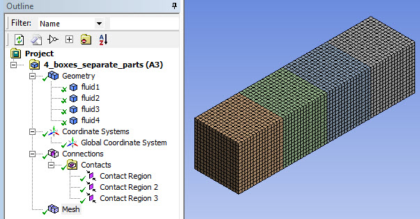
The first example is a model consisting of four separate single body parts in Ansys Workbench. The single body parts are named fluid1, fluid2, fluid3, and fluid4. The table below shows the geometry in Ansys Workbench and the corresponding part names that will appear in Ansys ICEM CFD:
| This geometry in Ansys Workbench... | Results in these part names in Ansys ICEM CFD... |
|---|---|
| A model consisting of four separate single body parts named: | |
| fluid1 | FLUID1_1 |
| fluid2 | FLUID2_2 |
| fluid3 | FLUID3_3 |
| fluid4 | FLUID4_4 |
The figure below shows the model after it was meshed in the Meshing application:
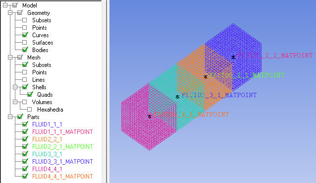
Next, the model was exported from the Meshing application to Ansys ICEM CFD format. In the figure below, the corresponding .prj file has been opened in Ansys ICEM CFD. Notice the names that are assigned to the various entities in the Ansys ICEM CFD format file:
Each body/part name has been suffixed with a unique integer to distinguish it from similarly named bodies/parts. (Note that in this example, part_name is equal to body_name.)
Each single body part in Ansys Workbench appears as <part_name>_<part_index> in the Ansys ICEM CFD format files. For example, the part named fluid1 in Ansys Workbench has a part name of FLUID1_1 in Ansys ICEM CFD, which appears as FLUID1_1_1 in the Ansys ICEM CFD format files after the part_index is added.
For each body in the Ansys Workbench file (fluid1, fluid2, fluid3, fluid4), a Material Point has been assigned (FLUID1_1_1_MATPOINT, FLUID2_2_1_MATPOINT, FLUID3_3_1_MATPOINT, FLUID4_4_1_MATPOINT).
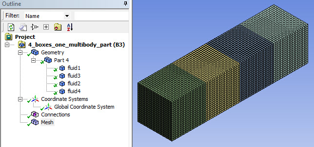
The second example is a model consisting of one multibody part in Ansys Workbench. The multibody part, which is named Part 4, contains four bodies named fluid1, fluid2, fluid3, and fluid4. The table below shows the geometry in Ansys Workbench and the corresponding part names that will appear in Ansys ICEM CFD:
| This geometry in Ansys Workbench... | Results in these part names in Ansys ICEM CFD (the / character denotes hierarchy)... |
|---|---|
| A model consisting of one multibody part named Part 4, containing four bodies named: | |
| fluid1 | PART_4_1/FLUID1_3 |
| fluid2 | PART_4_1/FLUID2_2 |
| fluid3 | PART_4_1/FLUID3_1 |
| fluid4 | PART_4_1/FLUID4_4 |
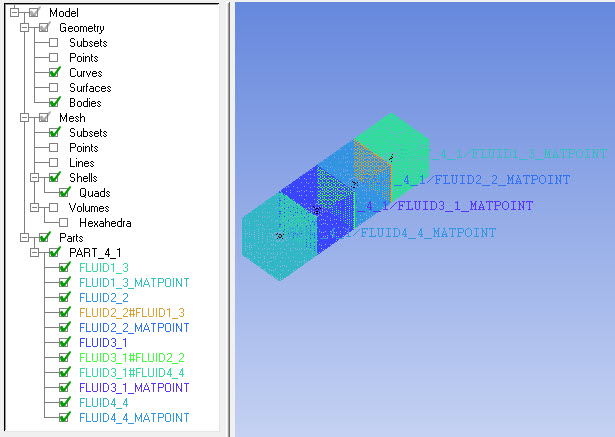
Next, the model was exported from the Meshing application to Ansys ICEM CFD format. In the figure below, the corresponding .prj file has been opened in Ansys ICEM CFD. Notice the names that are assigned to the various entities in the Ansys ICEM CFD format file:
Each body/part name has been suffixed with a unique integer to distinguish it from similarly named bodies/parts.
Each multibody part in Ansys Workbench appears as <part_name>_<part_index>/<body_name>_<body_index> in the Ansys ICEM CFD format files. For example, the fluid1 body in Part 4 in Ansys Workbench has a part name of PART_4_1/FLUID1_3 in the Ansys ICEM CFD format files.
The bodies that are in the multibody part in the Ansys Workbench file (fluid1, fluid2, fluid3, and fluid4) have been put into an Ansys ICEM CFD assembly named Part_4.
The faces that are shared between the various pairs of bodies have been named FLUID2_2#FLUID1_3, FLUID3_1#FLUID2_2, and FLUID3_1#FLUID4_4.
For each body in the Ansys Workbench file (fluid1, fluid2, fluid3, fluid4), a Material Point has been assigned (FLUID1_3_MATPOINT, FLUID2_2_MATPOINT, FLUID3_1_MATPOINT, FLUID4_4_MATPOINT).
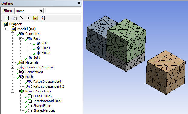
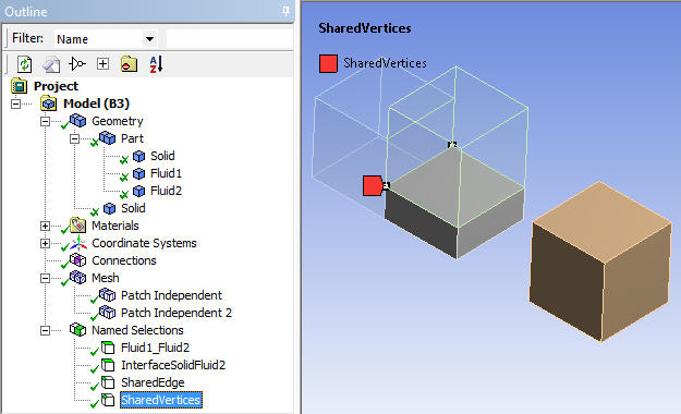
The third (and final) example involves a model for which four Named Selections are defined in the DesignModeler application. The model is meshed in the Meshing application, exported to Ansys ICEM CFD format, and opened in Ansys ICEM CFD.
The first figure shows the model after it was meshed in the Meshing application.
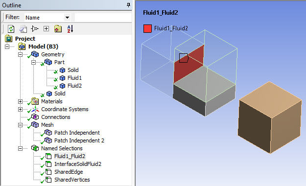
The next four figures show the entit(ies) in the model that are contained in each of the four Named Selections. In the figure below, the Fluid1_Fluid2 Named Selection is highlighted.
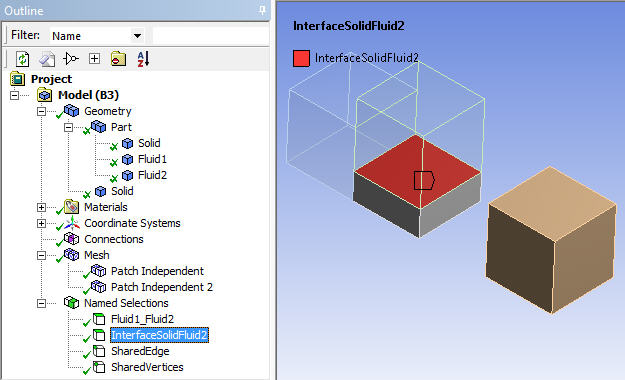
In the figure below, the InterfaceSolidFluid2 Named Selection is highlighted.
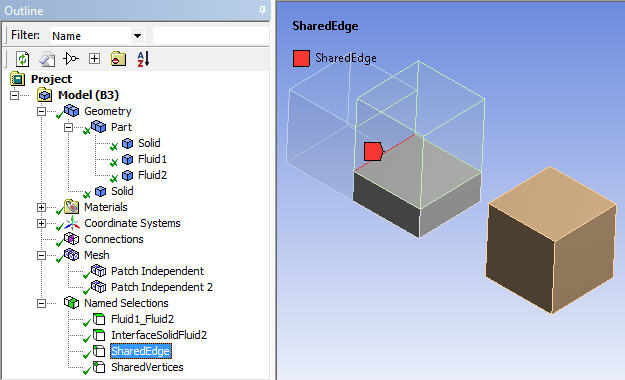
In the figure below, the SharedEdge Named Selection is highlighted.
In the figure below, the SharedVertices Named Selection is highlighted.
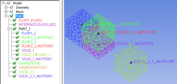
Next, the model was exported from the Meshing application to Ansys ICEM CFD format. In the figure below, the corresponding .prj file has been opened in Ansys ICEM CFD. Notice the names that are assigned to the various entities in the Ansys ICEM CFD format file:
Each body/part name has been suffixed with a unique integer to distinguish it from similarly named bodies/parts.
The bodies that are in the multibody part in the Ansys Workbench file (Solid, Fluid1, and Fluid2) have been put into an Ansys ICEM CFD assembly named Part_1.
The face that is shared between SOLID_1 and FLUID1_2 has been named SOLID_1#FLUID1_2.
Because Fluid1_Fluid2, InterfaceSolidFluid2, SharedEdge, and SharedVertices are all Named Selections in the Ansys Workbench file, each of them has been put into a separate Ansys ICEM CFD part.
For each body in the Ansys Workbench file (Solid, Fluid1, Fluid2, Solid), a Material Point has been assigned (SOLID_1_MATPOINT, FLUID1_2_MATPOINT, FLUID2_3_MATPOINT, and SOLID_2_1_MATPOINT).
Note: For additional information, refer to the documentation available under the Help menu within Ansys ICEM CFD.