You can use the Meshing application to export faceted geometry for use in Ansys Fluent Meshing (formerly TGrid):
Select from the main menu.
In the Save As dialog box, choose a directory and specify a file name for the file. Then choose TGrid Faceted Geometry File from the drop-down menu and click .
As a result, a file with the extension .tgf is created. The exported file can be imported into Ansys Fluent Meshing, where you can use such features as the Ansys Fluent Meshing wrapper utility.
Note: The .tgf file has the same format as a .msh file and will be recognized as a "Mesh File" when read into Ansys Fluent Meshing (File/Read/Mesh... menu item).
Upon export, Ansys Fluent Meshing objects and zones are created according to geometry bodies and Named Selections. Part and body names are used in the Ansys Fluent Meshing object/zone names to identify the parts and bodies from which they originated.
Remember the following information when exporting to Ansys Fluent Meshing:
The quality of the exported facets is derived from the CAD system. You can use the Facet Quality option () to control the quality of the exported facets (the higher the setting, the higher the quality). However, be aware that higher settings create large numbers of facets, which can slow down the Meshing application.
The part, body, and Named Selection names that were present in the Meshing application are exported in all lowercase characters for use in the corresponding Ansys Fluent Meshing zone names.
Only part and body names that were imported into the Meshing application are used in the exported zone name. For example, names that were initially defined in the Ansys DesignModeler application or initially appeared in the Tree Outline when a CAD file was loaded directly into the Meshing application will be used. Any subsequent renaming of parts and bodies that occurs in the Meshing application will not be taken into account in the exported zone names.
Vertices (regardless of whether they are contained in a Named Selection) are ignored.
The name of each Named Selection is filtered upon export such that only allowable characters remain in the name of the Ansys Fluent Meshing zone. Allowable characters include all alphanumeric characters as well as the following special characters:
_ + - : .
All other characters, including spaces, are invalid. If an invalid character is used, it is replaced by a hyphen (-) upon export.
When the same entity is a member of more than one Named Selection, those Named Selections are said to be "overlapping." If you are exporting faceted geometry into the Ansys Fluent Meshing format (or a mesh into the Ansys Polyflow, CGNS, or Ansys ICEM CFD format), and overlapping Named Selections are detected, the export will fail and you must resolve the overlapping Named Selections before proceeding. For details, see Repairing Geometry in Overlapping Named Selections.
The figures below illustrate the process of exporting geometry in faceted representation from the Meshing application to Ansys Fluent Meshing. Figure 23: Part, Body, and Named Selection Names in the Meshing Application shows the model in the Meshing application. The geometry consists of a multibody part named AeroValve, and the three bodies that AeroValve contains are named Outletbody, Valve, and Inletbody. Notice that three Named Selections have been defined and are highlighted in the Geometry window: Inlet, Outlet, and Valve_opening.
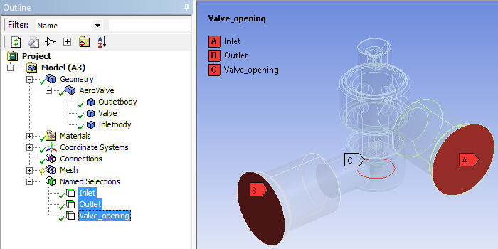
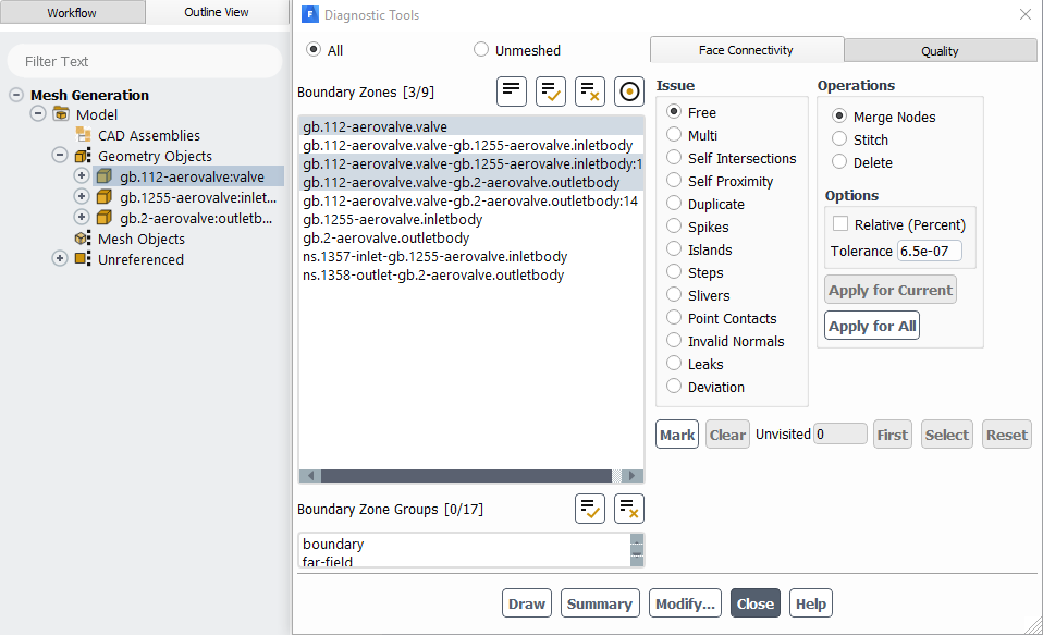
Figure 24: Objects/Zone Names Transferred to Ansys Fluent Meshing shows the Surface Retriangulation panel after the exported .tgf file is imported into Ansys Fluent Meshing.