


In BladeGen, you can create Flank Milled blades.
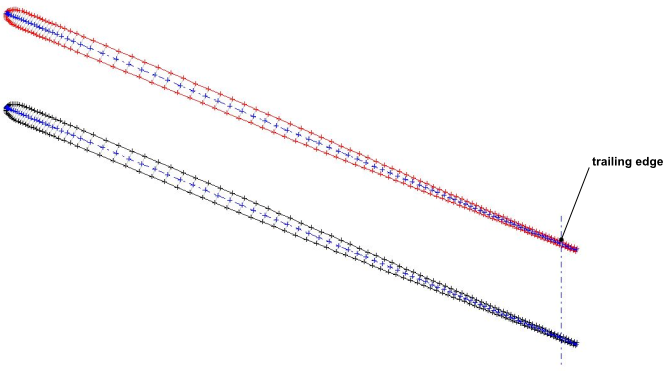
Flank milled blades represent a special case of blade geometry definition where the blade pressure and suction surfaces are described by only two layers, typically one at the hub and one at the shroud (or tip). During manufacture, the milling tool cuts the full depth of the blade passage at once, whereby the milling tool path is implicitly described by the ruling lines on the surface of the blade. These ruling lines give the surface a ‘ruled’ shape between the two defining layers. For cut-off blades, the ruling lines may extend beyond, and do not need to be parallel to, the cut-off end. For this reason the cut-off is typically created as a separate machining step.
In the current implementation, the endpoints of any given ruling line are constrained to be at the same normalized distance along the extended camberline (which includes the blade extension). Note that the milling machine will enforce some limitations on the rate of orientation change that is acceptable between adjacent ruling lines.
To begin making a Flank Milled blade, put BladeGen into Flank Milled mode by selecting Blade > Flank Milled. This command then displays a check mark next to it to indicate that BladeGen is operating in Flank Milled mode. To exit Flank Milled mode (for example, if it was selected in error), select the same command.
The requirements for activating Flank Milled Blade mode are listed in Table 9.14: Requirements for Activating Flank Milled Blade Mode. If the current blade, and/or any splitter blade, does not conform to the requirements of Flank Milled mode, BladeGen may, depending on the current settings:
Change one or more settings automatically and notify you of those changes via warning messages, or
Issue an error message upon selecting Flank milled mode and then not enter Flank Milled mode, or
Make the Flank Milled mode command unavailable.
Table 9.14: Requirements for Activating Flank Milled Blade Mode
|
Feature or Setting |
Requirement |
Automatically set by software? |
|---|---|---|
|
Defining Layers |
Only two defining layers: hub and either tip or shroud. Both have angle distributions; one or both have thickness definitions; no other layers can have angle or thickness definitions. |
Yes |
|
Output Layers |
Must include at least both defining layers. |
Yes |
|
LE/TE edges |
One must be cut-off, the other must be elliptical. When Flank Milled mode is enabled, BladeGen will check that the current blade's LE and TE style combination is supported. If the combination is not supported, an error message is issued and Flank Milled mode will not be entered. Note that when the LE an TE types are eligible, they are locked upon entering Flank Milled mode; in the Blade Property Dialog, the LE Type and TE Type settings are made read-only. 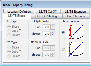 All blades (the main blade and all splitter blades) must have the same LE Type and also the same TE Type; if there are different LE types or different TE types, an error message is displayed. The elliptical edge must be straight as viewed in the R-Z plane. |
No |
|
Point Control Dialog > Point Distribution |
The point distribution is enforced to be Continuous.  You can adjust the (per layer) total number of points and the number of points that define the elliptical edge. |
Yes |
|
Mode |
You must use Angle/Thickness mode (Model > Mode > Ang/Thk Mode...). You cannot use Prs/Sct mode. |
No (In this case, the command for entering Flank Milled mode is unavailable.) |
Output
BladeGen has two sets of default output point values. One for the normal blade mode and one for the Flank Milled mode.
When you switch from normal mode to Flank Milled mode, BladeGen will change the output point values if they are less than the Flank Milled point defaults.
When you switch from Flank Milled mode to normal mode, BladeGen will change the output point values back to the normal defaults, and show a dialog to inform you that they have changed back to the default.
When exporting a Flank Milled blade to the TurboGrid Input File format, a set of files is written. One of those files contains profile data for each exported layer plus an additional set of points that defines the cut-off leading or trailing edge. Such data could be used by CAM milling software. For a Flank Milled blade, corresponding profile points (each point from a different output layer) are colinear.
Cut-off Edge of Blade(s)
To adjust the blade extension to the cut-off end, use the Blade > Flank Milled Blade Extension... command.
The Flank Milled Blade Extension... command, which is available only in Flank Milled mode, displays the Flank Milled Blade Extension dialog box, which accepts two numbers (Hub Layer and Shroud Layer) to control the lengths of the two respective surface ruling line extensions for the applicable blade: one on the hub layer, the other on the shroud (or shroud tip) layer.
Each extension is expressed as a fraction (between zero and one, default: 0.1) of a base length. All blades (including any splitter blades) use the same base length, which is the average meridional length of the main blade (the arithmetic average for the two defining layers).
When in the B2B View
You can view a defining layer but not any other layer.
Points are shown beyond the cut-off edge.
The throat calculation ignores the blade extension beyond the cut-off edge.
The centroid is not available for viewing.
When in the 3D View
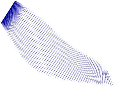
The Display Group Control Dialog can be set to show Ruling Lines for visualization purposes.
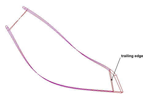
The cut-off location appears as part of the Blade group, which is controlled from the Display Group Control Dialog. Note that the cut-off location is shown using a simple quadrilateral whether or not the actual edge shape is linear in the R-Z plane.
The following limitations apply to Flank Milled blades in BladeGen:
Output of Flank Milled Blade data
Flank Milled blades can be exported only as Neutral Data Files (NDF files) or TurboGrid Input Files.
Comparison mode
Flank Milled blades cannot be compared using Comparison mode (File > Compare...).
Hub gap
There can be no gap between the blade and the hub.
Shroud gap
In order to create a gap between the blade and the shroud, you cannot use a meridional trim profile; instead, include an output layer at the span of the blade tip.