


The Blade feature is the geometry feature that is responsible for creating a blade or blade set. This feature defines the key properties of the blade, such as the blade type and the leading and trailing edge location and shape. A given Blade feature (and its child Splitter features) must not overlap with other Blade features (and their child Splitter features) within a given FlowPath.
Blade profiles can be defined in two ways:
By referring to angle and thickness definitions (CamThkDef sub-features: see Blades made using Camberline/Thickness Sub-features) to define the blade profiles, or
By referring to blade sections and their theta positions (Blade Section sub-features: see Blades made using Blade Section (Airfoil Design Mode) Sub-features).
When using the Camberline/Thickness blade design mode, the blade shape is defined on flow path layers according to angle and thickness definitions.
In the tree view, when using the Camberline/Thickness blade design mode, CamThkDef sub-features appear as sub-nodes of the Blade feature (or Splitter feature, if the Splitter is of Type "Independent"). For details on CamThkDef sub-features, see Camberline/Thickness Definition Sub-feature.
When using the Camberline/Thickness blade design mode, the feature properties of the Blade/Splitter feature are as follows:
|
Details of [Feature Name] | |
|
Blade |
[Feature Name] |
|
Operation |
[ Add Material | Add Frozen ] |
|
Blade Design Mode |
[ Camberline/Thickness | Airfoil ] |
|
Flow Path |
[FlowPath selection] |
|
Type |
[Rotor | Stator] |
|
Number of Blade Sets |
[Integer Value] |
|
Surface Construction |
[From Reference Blade | General | Ruled Element | Flank Milled | Radial Element | Axial Element | User Defined] Note that the |
|
Taper Angle (Only for "Surface Construction" set to "Axial Element") |
[Value] |
|
Angle Spanwise Distribution (Only for "Surface Construction" set to "User Defined") |
[General | Radial Element] |
|
Thickness Spanwise Distribution (Only for "Surface Construction" set to "User Defined") |
[Equation Driven] If you have loaded an NDF file from BladeGen, and the BladeGen definition contains a user-defined spanwise distribution of thickness, then property Thickness Spanwise Distribution is set to Equation Driven. For details, see User-Defined Spanwise Distribution in the TurboSystem User's Guide. |
|
Blade Extension (%) |
[Value] [a] |
|
Shroud Tip Clearance |
[None | Layer | Tip Gap] This property also affects any associated splitter blades. Note that the ExportPoints feature is not supported when using the |
|
Shroud Tip Layer (Only for "Shroud Tip Clearance" set to "Layer") |
Layer number at which to make a blade tip (at the shroud end of the blade). |
LE Gap (Only for "Shroud Tip Clearance" set to "Tip Gap") | [Value] This is the shroud clearance at the leading edge. The shroud clearance varies linearly with meridional coordinate. |
TE Gap (Only for "Shroud Tip Clearance" set to "Tip Gap") | [Value] This is the shroud clearance at the trailing edge. |
|
Hub Tip Clearance |
[None | Layer | Tip Gap] This property also affects any associated splitter blades. Note that the ExportPoints feature is not supported when using the |
|
Hub Tip Layer (Only for "Hub Tip Clearance" set to "Layer") |
Layer number at which to make a blade tip (at the hub end of the blade). |
LE Gap (Only for "Hub Tip Clearance" set to "Tip Gap") | [Value] This is the hub clearance at the leading edge. The hub clearance varies linearly with meridional coordinate. |
TE Gap (Only for "Hub Tip Clearance" set to "Tip Gap") | [Value] This is the hub clearance at the trailing edge. |
|
Hub Blend [b] | |
|
Blend Option |
[No | Constant Radius | Variable Blend] The default value is "No". Limitation: Hub Blend > Blend Option and Shroud Blend > Blend Option cannot both be set to Variable Blend at the same time. |
|
Rolling Ball Radius (Only for "Hub Blend > Blend Option" set to "Constant Radius") |
[Value] |
|
Approximation Angle (Only for "Hub Blend > Blend Option" set to "Constant Radius") |
[Value] The default value is 25 degrees. |
|
Approximation Radius Ratio (Only for "Hub Blend > Blend Option" set to "Constant Radius") |
[Value] |
|
Blend Shape Control (Only for "Hub Blend > Blend Option" set to "Variable Blend") |
[Shape Ratio | Rolling Ball Approximation] The default value is "Shape Ratio". |
|
Blend Shape Ratio (Only for "Blend Shape Control" set to "Shape Ratio") |
[0.01 <= Value <= 1.0, 0.5] |
|
Blade Hold Line Option (Only for "Blend Shape Control" set to "Shape Ratio") |
[Constant Span | Linearly Varying Span | Spline Curve] The blade hold line is a topological line that marks the edge of the blend where the blend meets the blade (or splitter of type "Independent"). For details, see Hub Blends and Shroud Blends. The shape of a variable blend depends partly on the blade hold line. Property "Blade Hold Line Option" determines the method for defining the blade hold line. For details, see Blade Hold Lines for Variable Hub Blends - Shape Ratio Option. |
|
Blade Hold Line Location (Only for "Blend Shape Control" set to "Shape Ratio" and "Blade Hold Line Option" set to "Constant Span") |
[0.01 < Value < 0.99, 0.1] |
|
Blade Hold Line Offset (Only for "Blend Shape Control" set to "Shape Ratio" and "Blade Hold Line Option" set to "Linearly Varying Span" or "Spline Curve") |
[By Span | By Distance] For details, see the description for "Blade Hold Line Option" above. |
|
By Span at Leading Edge (Only for "Blend Shape Control" set to "Shape Ratio" and "Blade Hold Line Option" set to "Linearly Varying Span" and "Blade Hold Line Offset" set to "By Span") |
[0.05 < Value < 0.99, 0.1] This is the normalized span value at the leading edge end of the blade hold line. For details, see the description for "Blade Hold Line Option" above. |
|
By Span at Trailing Edge (Only for "Blend Shape Control" set to "Shape Ratio" and "Blade Hold Line Option" set to "Linearly Varying Span" and "Blade Hold Line Offset" set to "By Span") |
[0.05 < Value < 0.99, 0.1] This is the normalized span value at the trailing edge end of the blade hold line. For details, see the description for "Blade Hold Line Option" above. |
|
By Distance at Leading Edge (Only for "Blend Shape Control" set to "Shape Ratio" and "Blade Hold Line Option" set to "Linearly Varying Span" and "Blade Hold Line Offset" set to "By Distance") |
[Value > 0, in session length unit] This is the absolute distance from the hub, measured along the leading edge. For details, see the description for "Blade Hold Line Option" above. |
|
By Distance at Trailing Edge (Only for "Blend Shape Control" set to "Shape Ratio" and "Blade Hold Line Option" set to "Linearly Varying Span" and "Blade Hold Line Offset" set to "By Distance") |
[Value > 0, in session length unit] This is the absolute distance from the hub, measured along the trailing edge. For details, see the description for "Blade Hold Line Option" above. |
|
Approximation Scale (Only for "Hub Blend > Blend Option" set to "Variable Blend") |
[1.00 <= Value <= 10.00, 3.5] |
|
Split Blade Faces at Hold Line (Only for "Hub Blend > Blend Option" set to "Variable Blend") |
[Yes | No] |
|
Shroud Blend [c] | |
|
Blend Option |
[No | Constant Radius | Variable Blend] The default value is "No". Limitation: Hub Blend > Blend Option and Shroud Blend > Blend Option cannot both be set to Variable Blend at the same time. |
|
Rolling Ball Radius (Only for "Shroud Blend > Blend Option" set to "Constant Radius") |
[Value] |
|
Approximation Angle (Only for "Shroud Blend > Blend Option" set to "Constant Radius") |
[Value] |
|
Approximation Radius Ratio (Only for "Shroud Blend > Blend Option" set to "Constant Radius") |
[Value] |
|
Blend Shape Ratio (Only for "Shroud Blend > Blend Option" set to "Variable Blend") |
[0.01 <= Value <= 1.0, 0.5] |
|
Span Location (Only for "Shroud Blend > Blend Option" set to "Variable Blend") |
[0.5 <= Value <= 0.99, 0.9] |
|
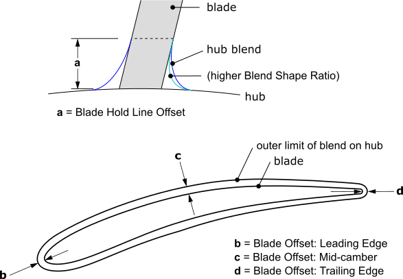
Blade Shroud Offset: Leading Edge (Only for "Shroud Blend > Blend Option" set to "Variable Blend") |
[Value >= 1E-3 mm, 1 mm] |
|
Blade Shroud Offset: Mid-camber (Only for "Shroud Blend > Blend Option" set to "Variable Blend") |
[Value >= 1E-3 mm, 1 mm] |
|
Blade Shroud Offset: Trailing Edge (Only for "Shroud Blend > Blend Option" set to "Variable Blend") |
[Value >= 1E-3 mm, 1 mm] |
|
Approximation Scale (Only for "Shroud Blend > Blend Option" set to "Variable Blend") |
[1.00 <= Value <= 10.00, 3.5] |
|
Flank Milled Extension (for flank milled only) For details, see Flank Milled Blades. | |
|
Hub Layer |
[ 0 < Value < 1.0, 0.1 ] |
|
Shroud Layer |
[ 0 < Value < 1.0, 0.1 ] |
|
Milling Line Control (for flank milled only) For details, see Flank Milled Blades. | |
|
Major Parameter |
[ -1.0 < Value < 1.0, 0.0 ] |
|
Minor Parameter |
[ -1.0 < Value < 1.0, 0.0 ] |
|
Leading Edge Details | |
|
Contour |
[Sketch selection] |
|
Type |
[Ellipse | Cut Off | Square] [d] |
|
Ellipse Ratio at Hub (for Ellipse only) |
[Value] |
|
Ellipse Ratio at Shroud (for Ellipse only) |
[Value] |
|
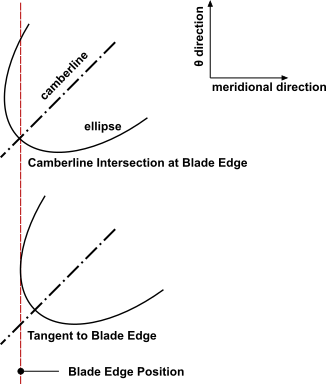
Ellipse Location |
[Camberline Intersection at Blade Edge | Tangent to Blade Edge] The leading edge curve is defined in the A-R view. At a given span, this curve defines the blade edge meridional position. The ellipse location is adjusted relative to the blade edge position.
The Camberline Intersection at Blade Edge option positions the ellipse so that the point where the ellipse intersects the camberline is at the blade edge position. The Tangent to Blade Edge option positions the ellipse so that it just touches a line drawn at the blade edge position. |
|
Trailing Edge Details | |
|
Contour |
[Sketch selection] |
|
Type |
[Ellipse | Cut Off | Square] [e] |
|
Ellipse Ratio at Hub (for Ellipse only) |
[Value] |
|
Ellipse Ratio at Shroud (for Ellipse only) |
[Value] |
|
Ellipse Location |
[Camberline Intersection at Blade Edge | Tangent to Blade Edge] See the description above for the corresponding Leading Edge Details property. |
|
Advanced Properties (Hidden by default) | |
|
Number of Points Along the Blade (for all blades but flank milled) |
[Int Value] This is the number of blade profile defining points used to construct the blade surfaces. This value is the number of points on a given side of the blade camberline. The profile points are defined symmetrically on either side of the camberline. |
|
Total Number of Points (for flank milled only) |
[18 <= Value, 100] This is the number of flank milled blade ruling lines used to define the blade surfaces, including lines in the flank milled extension. |
|
Number of Points for LE (for Ellipse only) |
[ 6 <= Value, 25 ] This is the number of blade profile defining points, on a given side of the camberline, used to construct an elliptical LE surface. |
|
Number of Points for TE (for Ellipse only) |
[ 6 <= Value, 25 ] This is the number of blade profile defining points, on a given side of the camberline, used to construct an elliptical TE surface. |
|
Camberline/Thickness Definitions: [number] | |
|
Layer 1 |
Yes |
|
Layer 2 |
[Yes | No] |
|
... |
[Yes | No] |
|
Layer n |
Yes |
[a] If the topology on the shroud end cap of the blade does not match the shroud topology (shroud contour edges), the blade has not been trimmed cleanly. In order to correct the trim, increase the Blade Extension.
The same applies for the hub end cap topology as compared with the hub topology (hub contour edges).
[b] See Figure 10.8: Hub Blend for the Blade: Constant Radius and Figure 10.9: Hub Blend for the Blade: Variable Blend using Shape Ratio.
[c] See Figure 10.8: Hub Blend for the Blade: Constant Radius and Figure 10.9: Hub Blend for the Blade: Variable Blend using Shape Ratio.
[d] Note that you cannot specify a perfectly sharp leading edge . As a workaround, you can specify a square leading edge with a small, but finite, thickness (for example, 0.05 mm).
[e] Note that you cannot specify a perfectly sharp trailing edge . As a workaround, you can specify a square trailing edge with a small, but finite, thickness (for example, 0.05 mm).
If your case involves features other than the Blade/Splitter, you can set the Operation feature property to "Add Frozen" to reduce computational time while you are designing the Blade/Splitter. However, with the "Add Frozen" option, bodies other than the Blade/Splitter will not be updated in response to changes in the Blade/Splitter. If you have other features that are dependent on the Blade/Splitter, you should set the Operation feature property to "Add Material" to allow the other features to be affected by the Blade/Splitter.
The FlowPath selection is the reference to the FlowPath feature, which is mandatory. Note that you can change a FlowPath selection only if the number of layers does not change.
The first Type property specifies whether the blade is a rotating or stationary component.
Before constructing the blade surface via lofting, BladeEditor interpolates lines that connect corresponding points on blade profiles. Each blade profile is governed by a CamThkDef sub-feature that defines a camberline, thickness distribution, and data controlling the number of profile points. In this section of the documentation, the term camberline refers to CamThkDef sub-feature.
The angle and/or thickness data of one profile may or may not be dependent on such data of another profile, depending on the Angle Definition and Thickness Definition settings of each camberline. Furthermore, the Angle Definition and Thickness Definition settings may be constrained to have particular values depending on the Surface Construction option.
The Surface Construction options are:
GeneralIf the Surface Construction property is set to
General, then no dependencies are enforced. Each camberline may be specified independently of the others.Ruled ElementIf the Surface Construction property is set to
Ruled Element, then you must use exactly two camberlines: one on the hub layer and one on the shroud layer. No other camberline is allowed.For the camberline on the hub layer, both Angle Definition and Thickness Definition are software-enforced to be User Specified.
For the camberline on the shroud layer, each of Angle Definition and Thickness Definition can be User Specified or Interpolated.
Flank MilledFlank milled blades represent a special case of blade geometry definition where the blade pressure and suction surfaces are described by only two layers, typically one at the hub and one at the shroud (or tip).
For details, see Flank Milled Blades.
Radial ElementIf the Surface Construction property is set to
Radial Element, then (by definition) all camberlines of the blade have the same theta value at any given axial coordinate. The Angle Definition is software-enforced to be User Specified for the camberline on the hub layer and Interpolated for each of the other camberlines.Figure 10.5: Contour plot of theta (θ) versus radial (R) and axial (Z) coordinates on a blade defined with
Radial Element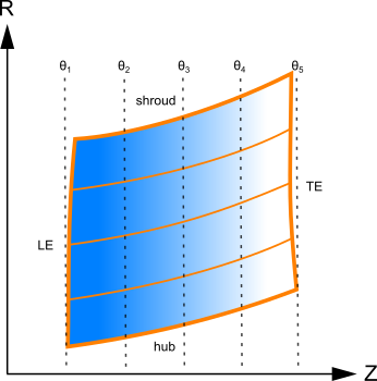
To ensure adequate interpolation accuracy (for the angle data) you should use at least five camberlines when using the
Radial Elementoption.In cases where the axial coordinate range of the camberline on the hub layer does not encompass the axial coordinate ranges of all other camberlines, the software will issue a warning message and might produce a faulty geometry. In such cases, you should consider using a different Surface Construction option.
If any part of the hub curve is aligned with the radial direction then the blade geometry is over-specified near the hub and the software might produce a faulty geometry.
Axial ElementIf the Surface Construction property is set to
Axial Element, then (by definition) all camberlines of the blade have the same theta value at any given radial coordinate. The Angle Definition and Thickness Definition are software-enforced to be User Specified for the camberline on the hub layer and Interpolated for each of the other camberlines. Blade thickness is reduced towards the shroud, with taper being applied linearly in the axial direction using the specified value of Thickness Taper Angle.Figure 10.6: Contour plot of theta (θ) versus radial (R) and axial (Z) coordinates on a blade defined with
Axial Element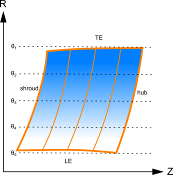
The primary advantage of an axial element design is that it enables a blade to be pulled axially out of the mold that forms it.
In cases where the radial coordinate range of the camberline on the hub layer does not encompass the radial coordinate ranges of all other camberlines, the software will issue a warning message and might produce a faulty geometry. In such cases, you should consider using a different Surface Construction option.
If any part of the hub curve is aligned with the axial direction then the blade geometry is over-specified near the hub and the software might produce a faulty geometry.
Note: When a curve in the angle or thickness view is modified, the properties displayed for the corresponding CamThkDef sub-feature are updated simultaneously, but the graphics view will not be updated until you regenerate the Blade.
The following topics are discussed:
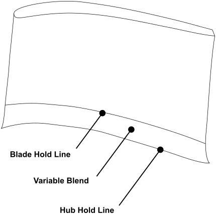
Figure 10.7: Hold Lines shows a hub blend and the hold lines that bound it topologically.
"Hub Blend" > "Blend Option" can be set to:
No
There is no hub blend.
Constant Radius
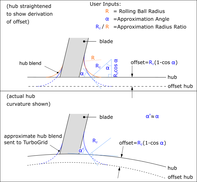
The hub blend is determined from the rolling ball process.
The relevant properties are Rolling Ball Radius, Approximation Angle, Approximation Radius Ratio.
Figure 10.8: Hub Blend for the Blade: Constant Radius shows how BladeEditor uses three user inputs to construct two versions of a hub blend: one for solid modeling (with radius of curvature R; this hub blend appears in the viewer), and one for export to TurboGrid (with radius of curvature R2; for meshing purposes, the angle at which this hub blend touches the hub,
 , must be non-zero).
Variable Blend
The hub blend is determined according to the "Hub Blend" > "Blend Shape Control" property option:
Shape Ratio
You define the hub hold line via sub-features of the blade. For details, see Hub Hold Lines for Variable Hub Blends - Shape Ratio Option.
You define the blade hold line either via properties or via sub-features of the blade, depending on property "Blade Hold Line Option". For details, see Blade Hold Lines for Variable Hub Blends - Shape Ratio Option.
The hub blend is determined from these hold lines and property "Blend Shape Ratio".
Figure 10.9: Hub Blend for the Blade: Variable Blend using Shape Ratio shows most of the properties that affect the shape of a variable hub blend that uses the Shape Ratio option.
Rolling Ball Approximation
The hub hold line, blade hold line, and shape of the hub blend are determined together using an approximation of the rolling ball process, where the ball radius is a function of normalized meridional coordinate.
Hub blend sub-features appear as sub-nodes of the Blade feature (or splitter of type " Independent"). These sub-features have names of the form "[blade name]_Hub_Blend_High" and "[blade name]_Hub_Blend_Low", with "High" and "Low" indicating the high-Theta and low-Theta sides of the blade, respectively. You edit these sub-features to specify the rolling ball radius as a function of normalized meridional coordinate. The X coordinate is the same as that used for the Shape Ratio option (see Hub Hold Lines for Variable Hub Blends - Shape Ratio Option). The Y coordinate is the rolling ball radius.
For variable hub blends:
For export to Ansys TurboGrid, the hub blend meets the hub at a finite angle, the general magnitude of which is controlled by the Approximation Scale property.
You can split blade faces at the blade hold line by setting "Split Blade Faces at Hold Line" to "Yes".
"Shroud Blend" > "Blend Option" can be set to:
No
There is no shroud blend.
Constant Radius
The shroud blend is determined from the rolling ball process.
The relevant properties are Rolling Ball Radius, Approximation Angle, Approximation Radius Ratio.
Figure 10.8: Hub Blend for the Blade: Constant Radius shows properties that affect the shape of a hub blend that uses the Constant Radius option. A constant radius shroud blend is similar. For details, see the description above for the constant radius hub blend.
Variable Blend
You define the blade hold line via the Span Location property, which sets the normalized span position of the blade hold line.
You define the shroud hold line via the Blade Shroud Offset properties.
The variable blend is determined from these hold lines and property "Blend Shape Ratio".
Figure 10.9: Hub Blend for the Blade: Variable Blend using Shape Ratio shows properties that affect the shape of a variable hub blend that uses the Shape Ratio option. A variable shroud blend is similar.
For export to Ansys TurboGrid, the shroud blend meets the shroud at a finite angle, the general magnitude of which is controlled by the Approximation Scale property.
The following topics are discussed:
For variable hub blends that use "Hub Blend" > "Blend Shape Control" set to "Shape Ratio", hub hold line sub-features appear as sub-nodes of the Blade feature (or splitter of type "Independent"). You can edit these sub-features to fine tune the shape of the hub hold line.
The "Hub Hold Line High" and "Hub Hold Line Low" sub-features each hold a set of points that collectively define a curve in X, Y coordinates. (Here, "High" and "Low" refer to the High Theta and Low Theta sides of the blade, respectively.) The curve implied by the points defines a hub hold line.
The X coordinate of the hold line varies linearly with meridional coordinate, from 0 percent at the leading edge to 100 percent at the trailing edge. The Y coordinate of the hold line represents the distance from the blade (without any blend) to the hub hold line, as measured along the hub, in the session length units. The minimum allowed Y coordinate is 1E-3 mm (or the equivalent in any other modeling unit).
You can add or delete points that define the hold line by right-clicking an existing point’s label, for example "Details of Blade1_Hub_Hold_Line_High: Offset Point 2", and using the shortcut menu.
Note the following:
At least 3 points are required to define the hold line.
Point labels are sequential and are subject to change when you add or delete a point.
You cannot delete a point that is parameterized.
For variable hub blends that use "Hub Blend" > "Blend Shape Control" set to "Shape Ratio", you can define the shape of the blade hold line in different ways, according to property "Blade Hold Line Option", which can be set to one of the following values:
Constant Span (default)
The "Constant Span" option offsets the blade hold line from the hub using a normalized span value ("Blade Hold Line Location").
Linearly Varying Span
The "Linearly Varying Span" option offsets the blade hold line from the hub using a measure that varies linearly with normalized meridional coordinate. You specify one value of this measure at each end (leading and trailing) of the blade hold line.
The type of measure depends on the "Blade Hold Line Offset" property:
If "Blade Hold Line Offset" = "By Span", the measure is normalized span value. The minimum allowed value is 1E-4.
If "Blade Hold Line Offset" = "By Distance", the measure is absolute distance along the spanwise direction, in the session length unit. The minimum allowed value is 1E-3 mm (or the equivalent in any other modeling unit).
Spline Curve
The "Spline Curve" option is like the "Linearly Varying Span" option except that you have more control of the hold line shape.
Blade hold line sub-features appear as sub-nodes of the Blade feature (or splitter of type "Independent"). You can edit these sub-features to fine tune the shape of the blade hold line.
The "Hub Blade Hold Line High" and "Hub Blade Hold Line Low" sub-features each hold a set of points that collectively define a curve in X, Y coordinates. (Here, "High" and "Low" refer to the High Theta and Low Theta sides of the blade, respectively. In addition, the word "Hub" refers to the hub end of the blade.) The curve implied by the points defines a blade hold line.
The X coordinate of the hold line varies linearly with meridional coordinate, from 0 percent at the leading edge to 100 percent at the trailing edge. The Y coordinate of the hold line controls the distance from the hub (without any blend) to the blade hold line, as measured along the spanwise direction.
The type of measure represented by the Y coordinate depends on the "Blade Hold Line Offset" property:
If "Blade Hold Line Offset" = "By Span", the measure is normalized span value.
If "Blade Hold Line Offset" = "By Distance", the measure is absolute distance along the spanwise direction, in the session length unit.
You can add or delete points that define the hold line by right-clicking an existing point’s label, for example "Details of Blade1_Hub_Blade_Hold_Line_High: Offset Point 2", and using the shortcut menu.
Note the following:
At least 3 points are required to define the hold line.
Point labels are sequential and are subject to change when you add or delete a point.
You cannot delete a point that is parameterized.
Blades must be made using Camberline/Thickness sub-features, not Blade Section (Airfoil Design Mode) sub-features.
Leading/trailing edges must be either rounded or cut-off, not square.
StageFluidZone feature generation might fail for some blades that have a hub blend or shroud blend; for such blades, you might need to set preference Improved Boolean Operations (Model Settings) to "Yes".
You might not be able to easily merge (using DesignModeler features) a SectorCut feature with a blade that has a hub blend; for such blades, you might need to set preference Improved Boolean Operations (Model Settings) to "Yes". For details, see SectorCut Feature.
It might be difficult to manually (using DesignModeler features) merge a SectorCut feature with a blade that has a shroud blend. You cannot merge a SectorCut feature with a blade that has a shroud blend by setting Improved Boolean Operations to ‘Yes’.
A hub cut (for the FlowPath feature) cannot be used with a blade that has a hub blend. A shroud cut cannot be used with a blade that has a shroud blend.
Hub Blend > Blend Option and Shroud Blend > Blend Option cannot both be set to Variable Blend at the same time.
For a blade with any hub/shroud blend, if the hub/shroud is highly curved near the leading/trailing edge of the blade then, in order to avoid problems with the blend geometry near the leading/trailing edge of the blade, you might have to set preference Improved Boolean Operations (Model Settings) to "No".
Note that changing preference Improved Boolean Operations can slightly affect the resulting geometry for blades that have a hub/shroud blend.
When a new blade or splitter is created, CamThkDef sub-features are created automatically for the Hub and Shroud layers. When a new layer is added to the flow path, the layer will appear in the Camberline Definitions group, but will be marked as 'No' to indicate that it is not a defining layer.
If you specify a curved leading or trailing edge contour, you must have at least three angle and/or thickness defining camberlines to create the desired blade shape. Furthermore, if you specify a cut-off leading or trailing edge and you do not have sufficient camberlines to follow the edge curvature, then the cut-off operation might fail. Adding additional camberline definitions (especially where the leading/trailing edge curve deviates the most from the blade shape) should fix this problem.
Whenever the Camberline Thickness Definition Layer property is set to ‘No’, no CamThkDef sub-feature exists under the Blade/Splitter for this layer. Also in this case, no information is displayed in the Angle, Thickness, or Auxiliary Views for this layer.
When a Camberline Thickness Definition Layer property is switched from 'No' to 'Yes', a CamThkDef sub-feature will be created for the Blade or Splitter, and the data will initially be interpolated from the existing blade data. The Angle Definition and Thickness Definition properties of the CamThkDef sub-feature will both be set to ‘User Specified’ so that the angle and thickness data is editable (otherwise it would remain interpolated from the existing blade data, but would be uneditable).
When a layer that was used for a CamThkDef sub-feature is removed from the flow path, the Blade or Splitter feature will generate an error. The error can be corrected by inserting a new layer in the flow path at the same layer index, or by switching the Camberline Thickness Definition Layer property for that layer to 'No' (therefore deleting the associated CamThkDef sub-feature). In the latter case, the layer will be removed from the list. If you insert more than one layer into the flow path after deleting a layer, the CamThkDef should be reconnected automatically to the layer with the closest average span value.
In BladeEditor, you can create flank milled blades. This option is applicable only to blades with one cut-off end.
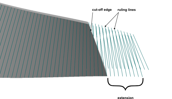
Flank milled blades represent a special case of blade geometry definition where the blade pressure and suction surfaces are described by only two layers, typically one at the hub and one at the shroud (or tip). During manufacture, the milling tool cuts the full depth of the blade passage at once, whereby the milling tool path is implicitly described by the ruling lines (milling lines) on the surface of the blade. These ruling lines give the surface a ‘ruled’ shape between the two defining layers. The ruling lines extend beyond, and do not need to be parallel to, the cut-off end. For this reason the cut-off is typically created as a separate machining step.
Flank milled blades are available for Blade and Splitter features that use the "Camberline/Thickness" blade design mode. To begin making a flank milled blade, set the Surface Construction property to "Flank Milled". Any splitter blades will automatically be flank milled via the "From Reference Blade" Surface Construction option.
The Flank Milled Extension properties, namely Hub Layer and Shroud Layer, control the lengths of profile extensions for the blade: one on the hub layer, the other on the shroud (or shroud tip) layer. The extensions allow ruling lines to be defined slightly beyond the cut-off edge (see Figure 10.10: Flank milled blade extension). Each extension length is interpreted as a fraction (between zero and one, default: 0.1) of a base length. All blades (including any splitter blades) use the same base length, which is the average meridional length of the main blade (the arithmetic average for the two defining layers).
Under the View menu, there is an option to turn on the visibility of the ruling lines, called Blade Ruling Lines.
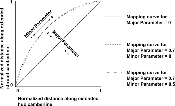
Except for near the leading edge, the ruling line endpoint distribution along the blade in the shroud layer is established by mapping from the distribution in the hub layer using a mapping curve. Figure 10.11: Ruling Line Orientation: Mapping Hub Endpoint to Shroud Endpoint shows example mapping curves. The mapping curve is specified by the Milling Line Control properties, namely Major Parameter and Minor Parameter. If Major Parameter is set to zero, then the two endpoints of any given ruling line are at approximately (neglecting influence from the leading edge region) the same normalized distance along the extended camberline (which includes the blade extension). Increasing the value of Major Parameter causes the shroud endpoints to move towards higher values of normalized meridional coordinate, that is, towards the trailing edge end of the extended camberline. Conversely, decreasing the value of Major Parameter has the opposite effect. Changing the value of Minor Parameter also affects endpoint spacing, provided that Major Parameter is set to a value other than zero.
Note that the milling machine will enforce some limitations on the rate of orientation change that is acceptable between adjacent ruling lines.
You can adjust the (per layer) total number of defining points and the number of points that define the elliptical edge.
Requirements For Flank Milled Blades:
There must be two defining layers: one at the hub and one at either the shroud tip or shroud. Both layers must have angle distributions; one or both have thickness distributions; no other layers can have angle or thickness definitions.
Either the leading edge or trailing edge must be elliptical; the other edge must be cut-off. The elliptical edge must be straight as viewed in the axial-radial plane.
Blade lofting is in the streamwise direction.
Limitations:
There can be no gap between the blade and the hub.
Blade Design Mode must be set to "Camberline/Thickness", not "Airfoil".
When using the Airfoil blade design mode, the blade shape is defined by a stacked sequence of airfoil sections. The airfoil sections are defined on the flow path layers, as with the Camberline/Thickness mode. The basic topology of each blade section (the set of edges that describe the shape of the airfoil) is defined by the section template, which is shown in Figure 10.12: Blade Section Sketch Template.
In the tree view, when using the Airfoil blade design mode, Blade Section sub-features appear as sub-nodes of the Blade feature . For details on Blade Section sub-features, see Blade Section (Airfoil Design Mode) Sub-feature.
When using the Airfoil blade design mode, the feature properties of the Blade feature are as follows:
|
Details of [Feature Name] | |
|
Blade |
[Feature Name] |
|
Operation |
[ Add Material | Add Frozen ] |
|
Blade Design Mode | [ Camberline/Thickness | Airfoil ] |
|
Section Orientation |
[ Positive | Negative ] |
|
Flow Path |
[FlowPath selection] |
|
Type |
[Rotor | Stator] |
|
Number of Blade Sets |
[Integer Value] |
|
Surface Construction | |
|
Blade Extension (%) |
[Value] [a] |
|
Shroud Tip Clearance |
[None | Layer | Tip Gap] This property also affects any associated splitter blades. Note that the ExportPoints feature is not supported when using the |
|
Shroud Tip Layer (Only for "Shroud Tip Clearance" set to "Layer") |
Layer number at which to make a blade tip (at the shroud end of the blade). |
LE Gap (Only for "Shroud Tip Clearance" set to "Tip Gap") | [Value] This is the shroud clearance at the leading edge. The shroud clearance varies linearly with meridional coordinate. |
TE Gap (Only for "Shroud Tip Clearance" set to "Tip Gap") | [Value] This is the shroud clearance at the trailing edge. |
|
Hub Tip Clearance |
[None | Layer | Tip Gap] This property also affects any associated splitter blades. Note that the ExportPoints feature is not supported when using the |
|
Hub Tip Layer (Only for "Hub Tip Clearance" set to "Layer") |
Layer number at which to make a blade tip (at the hub end of the blade). |
LE Gap (Only for "Hub Tip Clearance" set to "Tip Gap") | [Value] This is the hub clearance at the leading edge. The hub clearance varies linearly with meridional coordinate. |
TE Gap (Only for "Hub Tip Clearance" set to "Tip Gap") | [Value] This is the hub clearance at the trailing edge. |
|
Meridional Stacking Definitions | |
|
Stacking Method |
[LE/TE Contours] |
|
Section Reference Location |
[Section Origin | Airfoil Centroid | LE Camberline Point | TE Camberline Point | Chord Midpoint | Throat MidPoint ] |
|
LE Contour |
[Sketch selection] |
|
TE Contour |
[Sketch selection] |
|
Location |
[Inside Contours] |
|
Section Definitions [number] | |
|
Section1 on Layer1 |
[Yes] |
|
Section2 on Layer2 |
[Yes | No] |
| ... |
[Yes | No] |
| Sectionn on Layern |
[Yes] |
[a] If the topology on the shroud end cap of the blade does not match the shroud topology (shroud contour edges), the blade has not been trimmed cleanly. In order to correct the trim, increase the Blade Extension.
The same applies for the hub end cap topology as compared with the hub topology (hub contour edges).
If your case involves features other than the Blade/Splitter, you can set the Operation feature property to "Add Frozen" to reduce computational time while you are designing the Blade/Splitter. However, with the "Add Frozen" option, bodies other than the Blade/Splitter will not be updated in response to changes in the Blade/Splitter. If you have other features that are dependent on the Blade/Splitter, you should set the Operation feature property to "Add Material" to allow the other features to be affected by the Blade/Splitter.
The Section Orientation property specifies how the blade section is oriented with respect to the Theta direction. The choices are as follows:
Positive - makes the suction side of the blade face the low-Theta direction.
Negative - makes the suction side of the blade face the high-Theta direction.
When you make a change to the Section Orientation property, the section input data is preserved so that the section shape is effectively mirrored.
The FlowPath selection is the reference to the FlowPath feature, which is mandatory.
The Type property specifies whether the blade is a rotating or stationary component.
You can turn defining sections on or off from an existing airfoil design mode blade feature. This gives you flexibility in controlling the blade shape without having to recreate the blade feature.
You control which sections are defining sections in the details
view for the blade feature. The blade property group Section
Definitions lists all available sections. The property
value for each section has a Yes or No value depending on whether it is a defining section
(Yes) or not. When the blade feature is first
created, all sections are marked as defining sections. The hub (Layer1)
and shroud (Layern) are always defined.
If the flow path layers are modified, updating the blade feature shows any added sections in the blade Section Definitions. Newly added sections are marked as not defining sections unless you change the property value. Existing defining sections remain unchanged.
You cannot delete a flow path layer if a section is defined
on it. If a section definition is switched from Yes to No, the section data will be preserved (including
save/resume) until the flow path layer is deleted. Therefore, you
can switch it back to Yes, keeping the previous
data, as long as the layer still exists. The hub layer and shroud
layer are always defined.
In the details view, each section name includes the number of the layer on which the section is defined (for example, Section1 or Section2). In the tree view, under the blade feature, the only section sub-features listed are the defining sections; their names correspond with the names in the details view.
Note that Airfoil Design mode is not compatible with the following features:
Throat Area
Export Points (meanline)
Stage Fluid Zone
Vista TF Export
Splitter Blades
Radial Element Blades
Axial Element Blades
Neutral Data File (NDF) save and load