Opening the Static Structural system in the Mechanical editor, you will find an additional tab that gives you access to the Hydrodynamic Pressure Add-on.
Clicking the ![]() icon adds a
Hydrodynamic Pressure object to the Static Structural analysis.
icon adds a
Hydrodynamic Pressure object to the Static Structural analysis.
Alternatively, you can right-click the Static Structural analysis and select > from the context menu.
Note: Only one Hydrodynamic Pressure object may be added to a Static Structural analysis.
Note: Moonpool Pressures cannot be included in or mapped from Hydrodynamic Response systems.
You can configure the Hydrodynamic Pressure object using the options in its Details panel. The fields are described below.
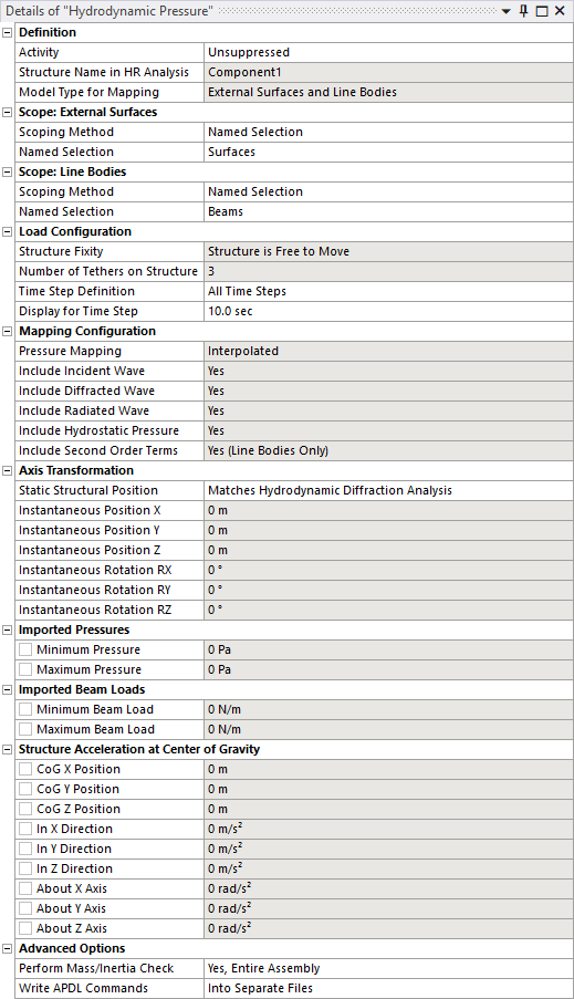
The Activity field allows you to set the suppression state of the Hydrodynamic Pressure object. Set to Suppressed if you want to exclude the object from the analysis.
Model Type indicates the types of loads that will be mapped from the Hydrodynamic Response analysis to the Static Structural analysis. Generally, it is possible to map pressures onto surfaces (Surface Bodies and the outer faces of Solid Bodies) and distributed loads onto beams or pipes (Line Bodies).
When Model Type includes External Surfaces, use Scope: Surfaces to select the surfaces that you want to map hydrodynamic pressures onto. Surfaces can be selected either by Named Selection, or by Geometry Selection from the graphical window.
When Model Type includes Line Bodies, use Scope: Line Bodies to select the beams or pipes that you want to map Morison loads onto. Line Bodies can be selected either by Named Selection, or by Geometry Selection from the graphical window.
When your time domain Hydrodynamic Response analysis contains more than one structure, you must select the name of the structure (in the Hydrodynamic Response system) that you intend to map loads from using the Structure Name in HR Analysis option.
The fixity of the selected structure in the Hydrodynamic Response analysis is indicated by Structure Fixity. When this field shows Structure is Fixed in Place, the radiated wave pressure component will be zero and no structure accelerations will be calculated. In this case, for consistency, the structure should also be fixed in the Static Structural analysis (for example, by a Fixed Support). If the Structure is Free to Move, you are recommended to use the Weak Springs option (in the Static Structural Analysis Settings) to mitigate rigid body motions.
If the selected structure has Internal Tanks associated with it in the Hydrodynamic Response analysis, the number of tanks is shown in the read-only Number of Internal Tanks field.
If the selected structure has Cables, Tethers or Joints attached to it in the Hydrodynamic Response analysis, the numbers of these features are shown in the read-only Number of Cables/Tethers/Joints on Structure fields.
If the selected structure has Morison Disc elements associated with it in the Hydrodynamic Response analysis, the number of discs is shown in the read-only Number of Morison Discs on Structure field.
The Time Step Definition option allows you to analyze either a single or multiple time steps from the time domain Hydrodynamic Response calculation within a single Static Structural analysis. The time steps available for pressure mapping are defined by the Time Domain Pressure Output [options in the time domain Hydrodynamic Response Analysis Settings.
When Time Step Definition is set to Single Time Step, use the Time Step option to select the time step for pressure mapping.
Setting Time Step Definition to Range of Time Steps allows you to define a First Time Step and Last Time Step for the pressure mapping.
To perform the Static Structural analysis over all available time steps, set Time Step Definition to All Time Steps.
Where multiple time steps are to be analyzed, the Static Structural Analysis Setting Number of Steps field will be updated automatically.
The additional option Display for Time Step can be used to set the time step at which the mapped pressures (in the graphical window) and output values (in the Details panel, described in Output: Imported Pressures, Imported Internal Tank Pressures, and Structure Acceleration at Center of Gravity) are shown.
The meshes in the Static Structural and Hydrodynamic Response systems are generally not coincident, which necessitates some approach to map the hydrodynamic pressures and Morison loads onto the structural mesh. For pressure mapping from a time domain Hydrodynamic Response system, the Pressure Mapping option is automatically set to Interpolated.
Hydrodynamic pressures at each node of the selected surfaces in the structural mesh are interpolated from the element-centered pressures calculated in the time domain Hydrodynamic Response analysis.
The mapped hydrodynamic loads will always include incident, diffracted, radiated and hydrostatic components, as indicated by the Include Incident/Diffracted/Radiated Wave and Include Hydrostatic Pressure fields. As noted above, if the Structure is Fixed in Place then the radiation component will be zero.
For distributed loads on Line Bodies, the forces per unit length along each line element (BEAM188/189 or PIPE288/289) are interpolated from the element-centered Morison forces calculated in the time domain Hydrodynamic Response analysis.
Note: Any moment acting about the centroid of each hydrodynamic line element is assumed to be negligible. It is therefore recommended to use a relatively small element size for Line Bodies in the hydrodynamic analysis.
Line body loads will only be transferred to line elements in the structural model that are exactly collinear with the Line Bodies of the hydrodynamic model (though the lengths of the line elements can be different between the hydrodynamic and structural meshes).
For Morison discs in the time domain Hydrodynamic Response analysis, forces and moments are directly applied to the nearest (ideally, coincident) mesh node in the structural model. You do not need to scope the Morison discs to the structural geometry. The Hydrodynamic Pressure object will automatically search through all the mesh nodes on Parts that are included in the load mapping selection.
Although you can share one Geometry source between the Hydrodynamic workflow and the Static Structural system, in the typical use case the Static Structural model will include internal and/or other structural components that are not required for the Hydrodynamic calculations. Depending on the context, the geometries in the Static Structural and Hydrodynamic systems may therefore employ different axis systems. To account for this, it is possible to define an axis transformation from the Static Structural geometry to the Hydrodynamic geometry.
Where the axis systems are consistent between the two analyses, the Static Structural Position may be set as Matches Hydrodynamic Diffraction Analysis. Otherwise, this option should be set to Differs from Hydrodynamic Diffraction Analysis, and Structure Position/Rotation Offsets should be defined for the translational and rotational freedoms. Offsets are defined relative to the Hydrodynamic Diffraction global axis system (FRA).
The position of the selected structure at the displayed time step is reported in the Instantaneous Position/Rotation fields, expressed in the Static Structural axis system (i.e. accounting for any defined Structure Position/Rotation Offsets). For reference, the mean water surface is drawn relative to the position of the structure.
The Minimum and Maximum Pressures on diffracting panel elements are reported. When Model Type includes Internal Tanks, the Minimum and Maximum Internal Tank Pressures are provided. When Model Type includes Line Bodies, the Minimum and Maximum Beam Loads (as Force per unit Length) are also shown.
For all cases, the position of the structure's center of gravity (in the Static Structural axis system), and the resultant translational and rotational accelerations about that center of gravity, are displayed. Where applicable, values are displayed for the time step selected in Display for Time Step.
The Hydrodynamic Pressure object accesses a Part's material properties so that it can estimate the mass, inertia, and center of gravity (CoG) position of the Part, and compare these to the corresponding properties from the hydrodynamic model. Generally, we want the force and moment reactions on any defined boundary conditions to be relatively small in the Static Structural system, and this check helps to ensure that the applied loads and accelerations are well-balanced.
The Perform Mass/Inertia Check setting can be used to adjust the behavior of the Hydrodynamic Pressure object in this respect. This setting has 4 options:
Yes, Entire Assembly: The mass/inertia/CoG of the entire assembly, including all Parts in the Geometry, will be calculated and compared to the corresponding properties of the selected structure in the upstream hydrodynamic analysis.
Yes, Selected Parts Only: The mass/inertia/CoG will be calculated and compared only for the Parts that are included in the Hydrodynamic Pressure, Internal Tank Pressure, Moonpool Pressure, Cable Force, Joint Force, and Tether Force selections.
No, Use Hydrodynamic Model CoG Position: The mass/inertia/CoG will not be calculated. The accelerations included by the Hydrodynamic Pressure object will be applied about the CoG position of the selected structure in the upstream hydrodynamic analysis (accounting for any defined Axis Transformation). You must ensure that the mass properties are consistent between the hydrodynamic and structural models.
No, Exclude Accelerations: The mass/inertia/CoG will not be calculated, and the Hydrodynamic Pressure object will not apply any accelerations in the structural analysis. You must ensure that the mass properties are consistent between the hydrodynamic and structural models.
In some cases, a Part's material properties may be inaccessible. For example, where Ansys Composite PrepPost (ACP) has been used to define a composite material, or where the structural analysis employs a material with no density value defined. For these cases, the Perform Mass/Inertia Check option must be set to No, Use Hydrodynamic Model CoG Position or No, Exclude Accelerations. The force/moment reactions on any defined boundary conditions must be checked carefully.
The Write APDL Commands option defines where the APDL commands (SFE, SFBEAM, etc.) associated with the mapped hydrodynamic loads are written. By default, these commands will be written Into Separate Files, which are referred to within the Mechanical input file using the /INPUT command. Alternatively, you can choose to write commands Direct to Mechanical Input File, so that no new files are created, though the Mechanical input file may become very large for an analysis with many load cases.
Once the Hydrodynamic Pressure object has been configured as required, right-click the Hydrodynamic Pressure object and select Generate to start the load transfer process. This involves two main steps:
Using the Ansys solver to determine the structural mass properties, which are compared to the mass properties from the time domain Hydrodynamic Response calculation.
Reading the output of the time domain Hydrodynamic Response calculation to determine hydrodynamic pressures at the structural mesh nodes and calculate translational and rotational accelerations to balance inertial loads.
Note: The Hydrodynamic Pressure Add-on will take into account any difference in the unit systems that are employed in the time domain Hydrodynamic Response and Static Structural systems.
Where the attached Geometry includes a large number of parts or bodies (1000 or more), the Mechanical UI may be noticeably unresponsive for some time during Hydrodynamic Pressure Generate and Solve operations. If necessary, you can monitor progress via the Log File, accessible through the Workbench menubar: > .
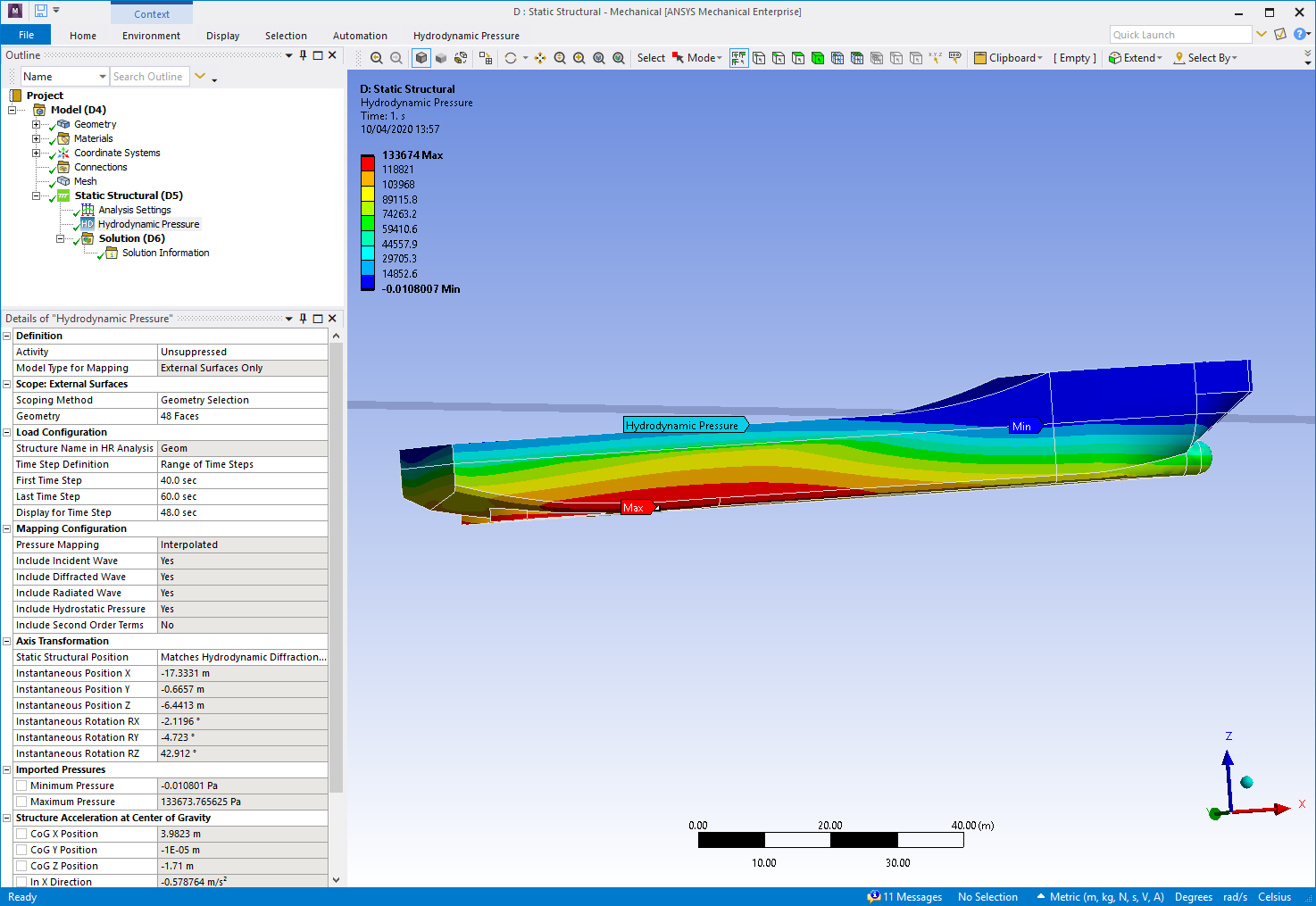
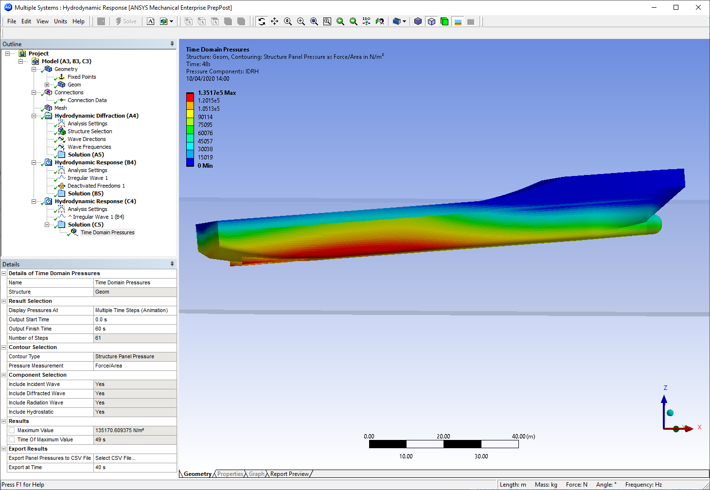
The transferred pressures are displayed in the graphical window (Figure 8.10: Hydrodynamic Pressures in the Static Structural System), and can be compared to the Structure Panel Pressures (Figure 8.11: Hydrodynamic Pressures in the Time Domain Hydrodynamic Response System) shown in the Time Domain Pressures result object in the upstream Hydrodynamic Response system.
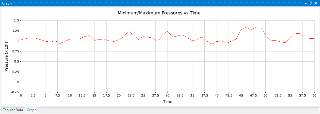
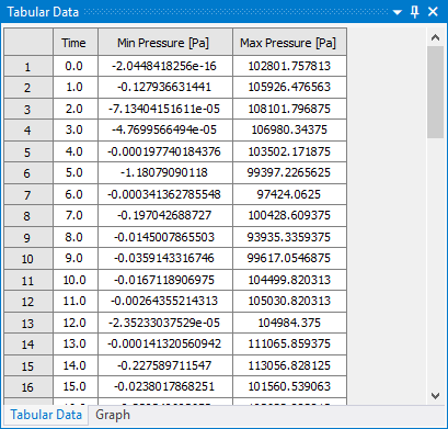
Where the Time Step Definition option is set to Range of Time Steps or All Time Steps, the minimum and maximum pressures (on surfaces) are shown over the mapping duration in graphical and tabular form.