Opening the Static Structural system in the Mechanical editor, you will find an additional tab that gives you access to the Hydrodynamic Pressure Add-on.
Clicking the ![]() icon adds a Hydrodynamic Pressure object to the
Static Structural analysis.
icon adds a Hydrodynamic Pressure object to the
Static Structural analysis.
Alternatively, you can right-click the Static Structural analysis and select > from the context menu.
Note: It is only possible to add one Hydrodynamic Pressure object to a Static Structural analysis.
In the Details of Hydrodynamic Pressure panel, you will find options that allow you to configure the Hydrodynamic Pressure object. These are described below.
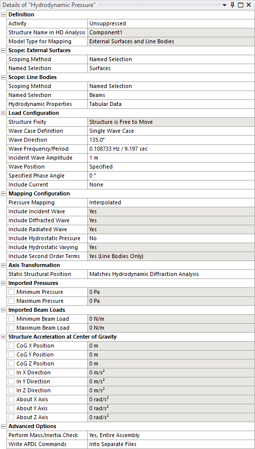
The Activity field allows you to set the suppression state of the Hydrodynamic Pressure object. Set to Suppressed if you want to exclude the object from the analysis.
Model Type indicates the types of loads that will be mapped from the Hydrodynamic Diffraction analysis to the Static Structural analysis. Generally, it is possible to map pressures onto surfaces (Surface Bodies and the outer faces of Solid Bodies) and distributed loads onto beams or pipes (Line Bodies).
When Model Type includes External Surfaces, use Scope: Surfaces to select the surfaces that you want to map hydrodynamic pressures onto. Surfaces can be selected either by Named Selection, or by Geometry Selection from the graphical window.
When Model Type includes Line Bodies, use Scope: Line Bodies to select the beams that you want to map hydrodynamic loads onto. Line Bodies can be selected either by Named Selection, or by Geometry Selection from the graphical window. You must also define viscous drag and inertia coefficients for the different cross sections that are included in your selection. These coefficients are used to calculate distributed loads on beams according to the Morison equation described in Theory. The Hydrodynamic Properties table sets coefficients for each cross section type. For non-cylindrical cross sections (solid rectangular and rectangular tube) you must define separate viscous drag and inertia coefficients for each transverse direction.
When your Hydrodynamic Diffraction analysis contains more than one structure, you must select the name of the structure (in the Hydrodynamic Diffraction system) that you intend to map loads from using the Structure Name in HD Analysis option.
The fixity of the selected structure in the Hydrodynamic Diffraction analysis is indicated by Structure Fixity. When this field shows Structure is Fixed in Place, the radiated wave pressure component will be zero and no structure accelerations will be calculated. In this case, for consistency, the structure should also be fixed in the Static Structural analysis (for example, by a Fixed Support). If the Structure is Free to Move you are recommended to use the Weak Springs option (in the Static Structural Analysis Settings) to mitigate rigid body motions.
If the selected structure has Internal Tanks associated with it in the Hydrodynamic Diffraction analysis, the number of tanks is shown in the read-only Number of Internal Tanks field.
If the selected structure has Moonpools associated with it in the Hydrodynamic Diffraction analysis, the number of Moonpools is shown in the read-only Number of Moonpools field.
If a forward speed has been defined in the Hydrodynamic Diffraction analysis, this is shown in Forward Speed in HD Analysis.
The Wave Case Definition option allows you to analyze either single or multiple wave conditions within a single Static Structural analysis.
When Wave Case Definition is set to Single Wave Case, the Wave Direction and Wave Frequency/Period fields are used to select a frequency/direction pair at which the hydrodynamic pressures acting on the structure will be evaluated. If a forward speed has been defined in the Hydrodynamic Diffraction analysis, the Encounter Frequency for this frequency/direction pair is also shown.
Setting Wave Case Definition to Single Frequency, All Directions, and selecting a single Wave Frequency/Period value, causes the Static Structural analysis to be performed for all wave directions at that wave frequency. Similarly, a Wave Case Definition of Single Direction, All Frequencies allows you to analyze over all wave frequencies for a given Wave Direction.
To perform the Static Structural analysis over all frequency/direction pairs in the Hydrodynamic Diffraction analysis, set Wave Case Definition to All Frequencies, All Directions.
For all wave case configurations, an Incident Wave Amplitude should be specified.
The Wave Position allows you to choose between single or multiple wave phase angles in the Static Structural analysis. When this option is set to Specified, use the Specified Phase Angle field to define the (single) wave phase angle. When Wave Position is set to Sequence, the Static Structural analysis will be carried out over multiple phase angles spaced equally over the wave cycle (from 0° to 360°); use the Number of Phase Increments field to set the number of steps. Alternatively, setting Wave Position to 0° (Real) and 90° (Imaginary) causes the analysis to be carried out over only these two phase angles. This last option is only applicable to linear cases (no beam loads).
Note: When the selected Structure is part of an interacting structure group in the upstream Hydrodynamic Diffraction analysis, there may be an offset between the reference points of the wave phase angles in the two systems. In the Hydrodynamic Diffraction analysis, the phase angle will be relative to the center of gravity of the first structure in the interacting structure group; in the Static Structural analysis the Wave Position or Specified Phase Angle will always be relative to the selected structure center of gravity.
Where multiple phase angles and/or multiple frequency/direction pairs are to be analyzed, the Static Structural Analysis Setting Number of Steps field will be updated automatically. For example: for a Hydrodynamic Diffraction analysis containing 20 wave frequencies and 13 wave directions, with the Wave Case Definition set to All Frequencies, All Directions and Number of Phase Increments set to 12, the total Number of Steps in the Static Structural analysis will be 20 x 13 x 12 = 3120.
The additional options Display for Wave Case and Display Pressures/Accelerations At can be used to set the wave case and wave phase angle at which the mapped pressures (in the graphical window) and output values (in the Details panel, described in Output: Imported Pressures, Loads, and Structure Acceleration at Center of Gravity) are shown.
When Model Type includes Line Bodies, a constant or profiled current can be included by creating an Ocean Current object in the Static Structural analysis and selecting that object from the Include Current drop-down menu.
The meshes in the Static Structural and Hydrodynamic Diffraction systems are generally not coincident, which necessitates some approach to map the hydrodynamic pressures onto the structural mesh. The Pressure Mapping option can be set to Interpolated or Direct.
Using the interpolated method, hydrodynamic pressures at each node of the selected surfaces in the structural mesh are interpolated from the element-centered pressures calculated in the Hydrodynamic Diffraction analysis. This method can be used for models that include Line Bodies in the load mapping selection. However, the accuracy of the method is inherently limited by the interpolation of the pressure data and is dependent on the resolution of the mesh in the Hydrodynamic Diffraction analysis. Furthermore, the interpolated method cannot be used for mapping onto the outer surfaces of Solid Bodies, or where the Hydrodynamic Diffraction analysis contains more than one structure.
Where the direct method is used, hydrodynamic pressure components at the position of each selected node are evaluated directly from the diffracting panel source strengths calculated in the Hydrodynamic Diffraction analysis. If the Hydrodynamic Diffraction analysis contains multiple structures, it is possible to use the direct method to map pressures onto one of those structures in the Static Structural system. The direct method also permits mapping onto the outer surfaces of Solid Bodies. This method avoids the loss of accuracy due to interpolation, but it cannot be used to map loads onto Line Bodies.
Internal Tank Pressures always use an interpolation method for mapping between the hydrodynamic and structural models. Moonpool Pressures always use a direct mapping method. These are independent of the Pressure Mapping setting described above.
Regardless of the selected method, the mapped hydrodynamic loads will always include incident, diffracted and radiated components, as indicated by the Include Incident/Diffracted/Radiated Wave fields. As noted above, if the Structure is Fixed in Place then the radiation component will be zero. Hydrostatic pressure can be optionally added by setting Include Hydrostatic Pressure to Yes. The hydrostatic-varying pressure component is always included when the interpolated method is used but is optional for the direct method. Second order pressure terms on diffracting panels are not calculated, but Line Body loads do include a second order viscous drag component.
Although you can share one Geometry source between the Hydrodynamic Diffraction and Static Structural systems, in the typical use case, the Static Structural model will include internal and/or other structural components that are not required for the Hydrodynamic Diffraction calculation. Depending on the context, the geometries in the Static Structural and Hydrodynamic Diffraction systems may therefore employ different axis systems. To account for this, it is possible to define an axis transformation from the Static Structural analysis to the Hydrodynamic Diffraction analysis.
Where the axis systems are consistent between the two analyses, the Static Structural Position may be set as Matches Hydrodynamic Diffraction Analysis. Otherwise, this option should be set to Differs from Hydrodynamic Diffraction Analysis, and Structure Position/Rotation Offsets should be defined for the translational and rotational freedoms. Offsets are defined relative to the Hydrodynamic Diffraction global axis system (FRA).
When Model Type includes External Surfaces, the Minimum and Maximum Pressures on diffracting panel elements are reported. When Model Type includes Internal Tanks, the Minimum and Maximum Internal Tank Pressures are provided. When Model Type includes Moonpools, the Minimum and Maximum Moonpool Pressures are stated. When Model Type includes Line Bodies, the Minimum and Maximum Beam Loads (as Force per unit Length) are also shown.
For all cases, the position of the structure's center of gravity (in the Static Structural axis system), and the resultant translational and rotational accelerations about that center of gravity, are displayed. Where applicable, values are displayed for the wave case and phase angle selected in Display for Wave Case and Display Pressures/Accelerations At Phase Angle, respectively.
The Hydrodynamic Pressure object accesses a Part's material properties so that it can estimate the mass, inertia, and center of gravity (CoG) position of the Part, and compare these to the corresponding properties from the hydrodynamic model. Generally, we want the force and moment reactions on any defined boundary conditions to be relatively small in the Static Structural system, and this check helps to ensure that the applied loads and accelerations are well-balanced.
The Perform Mass/Inertia Check setting can be used to adjust the behavior of the Hydrodynamic Pressure object in this respect. This setting has 4 options:
Yes, Entire Assembly: The mass/inertia/CoG of the entire assembly, including all Parts in the Geometry, will be calculated and compared to the corresponding properties of the selected structure in the upstream hydrodynamic analysis.
Yes, Selected Parts Only: The mass/inertia/CoG will be calculated and compared only for the Parts that are included in the Hydrodynamic Pressure, Internal Tank Pressure, Moonpool Pressure, Cable Force, Joint Force, and Tether Force selections.
No, Use Hydrodynamic Model CoG Position: The mass/inertia/CoG will not be calculated. The accelerations included by the Hydrodynamic Pressure object will be applied about the CoG position of the selected structure in the upstream hydrodynamic analysis (accounting for any defined Axis Transformation). You must ensure that the mass properties are consistent between the hydrodynamic and structural models.
No, Exclude Accelerations: The mass/inertia/CoG will not be calculated, and the Hydrodynamic Pressure object will not apply any accelerations in the structural analysis. You must ensure that the mass properties are consistent between the hydrodynamic and structural models.
In some cases, a Part's material properties may be inaccessible. For example, where Ansys Composite PrepPost (ACP) has been used to define a composite material, or where the structural analysis employs a material with no density value defined. For these cases, the Perform Mass/Inertia Check option must be set to No, Use Hydrodynamic Model CoG Position or No, Exclude Accelerations. The force/moment reactions on any defined boundary conditions must be checked carefully.
Once the Hydrodynamic Pressure object has been configured as required, right-click the Hydrodynamic Pressure object and select Generate to start the load transfer process. This involves two main steps:
Using the Ansys solver to determine the structural mass properties, which are compared to the mass properties from the Hydrodynamic Diffraction calculation;
Reading the output of the Hydrodynamic Diffraction calculation to determine hydrodynamic pressures at the structural mesh nodes and calculate translational and rotational accelerations to balance inertial loads;
Note: The Hydrodynamic Pressure Add-on will take into account any difference in the unit systems that are employed in the Hydrodynamic Diffraction and Static Structural systems.
Where the attached Geometry includes a large number of parts or bodies (1000 or more), the Mechanical UI may be noticeably unresponsive for some time during Hydrodynamic Pressure Generate and Solve operations. If necessary, you can monitor progress via the Log File, accessible through the Workbench menubar: > .
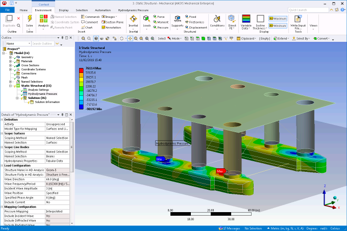
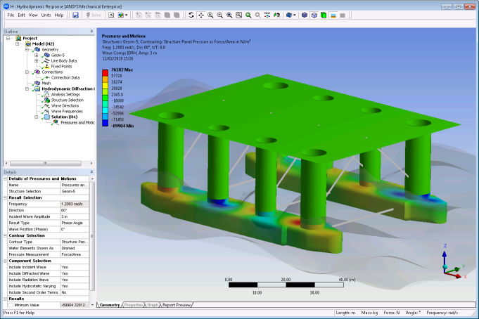
The transferred pressures are displayed in the graphical window (Figure 8.5: Hydrodynamic Pressures in the Static Structural System), and can be compared to the Structure Panel Pressures (Figure 8.6: Hydrodynamic Pressures in the Hydrodynamic Diffraction System) shown in the Pressures and Motions result object in the upstream Hydrodynamic Diffraction system.
Note:
The pressure Component Selection in the Pressures and Motions object may need to be matched to those included in the Hydrodynamic Pressure object for such a comparison to be made.
When the selected Structure is part of an interacting structure group in the upstream Hydrodynamic Diffraction analysis, there may also be an offset between the reference points of the wave phase angles in the two systems. In the Hydrodynamic Diffraction analysis, the phase angle will be relative to the center of gravity of the first structure in the interacting structure group; in the Static Structural analysis the phase angle will always be relative to the selected structure center of gravity. This may mean that the transferred pressures do not appear to match for a given Wave Position or Specified Phase Angle; it is then necessary to determine a phase angle offset from the wavelength (for the selected Wave Frequency) and the distance (in the selected Wave Direction) between the interacting structure group first structure center of gravity and the selected structure center of gravity.
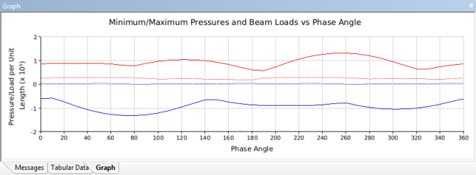
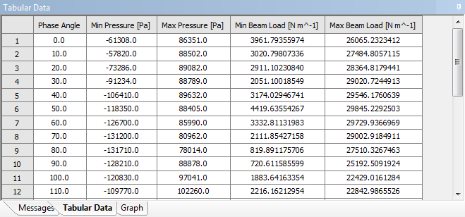
Where the Wave Position option is set to Sequence, the minimum and maximum pressures (on surfaces) and/or beam loads (on line elements) are shown over the wave cycle in graphical and tabular form.