


This window lets you select the Predef you want to use for the 3D Part you are creating.
Click one of the six buttons at the top of this window to select your Predef :
Box
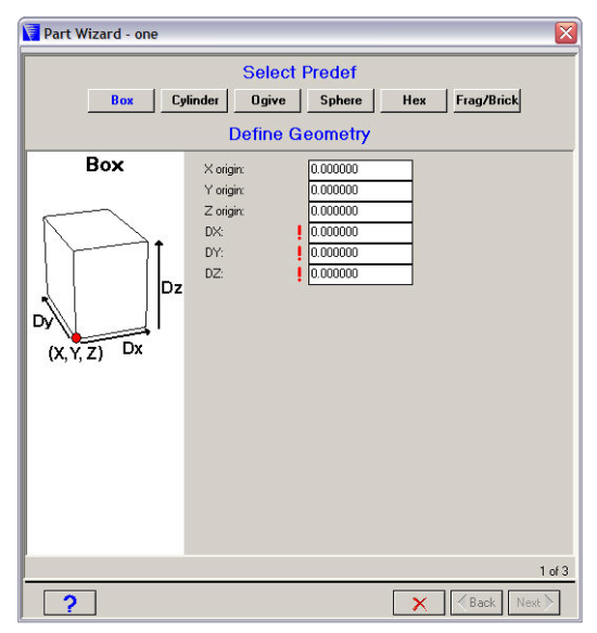
This predef is a box with its axes parallel to the X and Y axes.
- Origin
The X, Y, and Z coordinates of the lower corner of the box.
- Box Dimensions
The dimensions of the box (DX, DY, DZ).
Cylinder
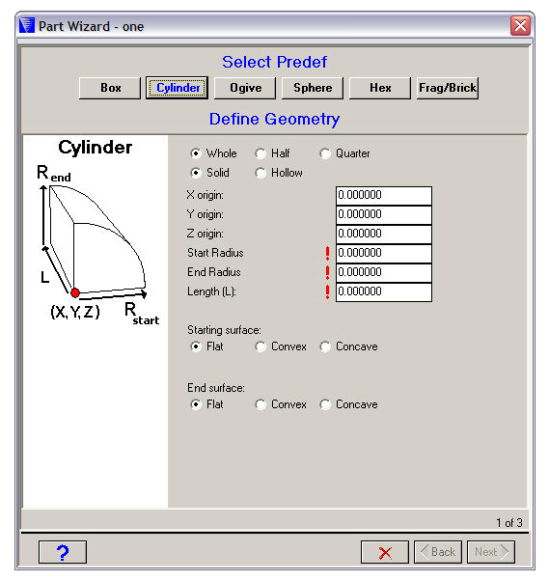
This predef is a cylinder with its axis parallel to the Z axis.
- Section
The section you want to generate (Whole, Half or Quarter). This should match any symmetry planes you have defined for your model.
- Solid or Hollow
Choose either a solid or hollow cylinder.
If you choose a hollow cylinder, you will have to specify inner and outer radii for the cylinder.
- Origin
The X, Y, and Z coordinates for the center of the starting surface of your cylinder.
- Start Radius / End Radius
You can specify different radii for the starting and end faces of your cylinder. For a regular cylinder (constant radius), set the starting radius equal to the end radius.
- Length
The length of your cylinder.
- Start Surface / End surface
The starting and end surfaces of your cylinder can be flat, concave or convex.
If you select a concave or convex surface, you will have to specify its radius of curvature.
Ogive
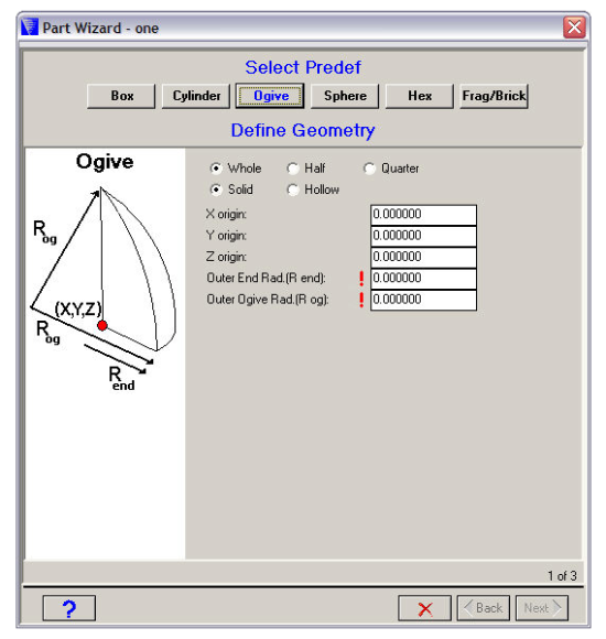
This predef is an ogive with its axis parallel to the Z axis.
- Section
The section you want to generate (Whole, Half or Quarter). This should match any symmetry planes you have defined for your model.
- Solid or Hollow
Choose either a solid or hollow ogive.
If you choose a hollow ogive, you will have to specify inner and outer radii for the ogive.
- Origin
The X, Y, and Z coordinates for the center of your ogive.
- End Radius
The end radius of your ogive.
- Ogive Radius
The ogive radius.
Sphere
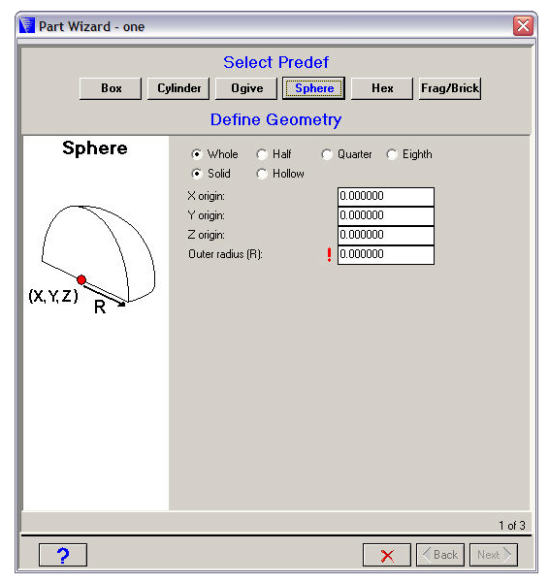
This predef is a sphere.
- Section
The section you want to generate (Whole, Half, Quarter or Eighth). This should match any symmetry planes you have defined for your model.
- Solid or Hollow
Choose either a solid or hollow sphere.
If you choose a hollow sphere, you will have to specify inner and outer radii for the sphere.
- Origin
The X, Y, and Z coordinates for the center of the sphere.
- Radius
The radius of the sphere.
Hex
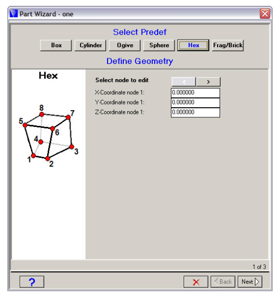
- Select Node to Edit
Use the arrow buttons to select each of the eight nodes in turn.
- Coordinates
The X, Y, and Z coordinates of the node.
Frag/Brick
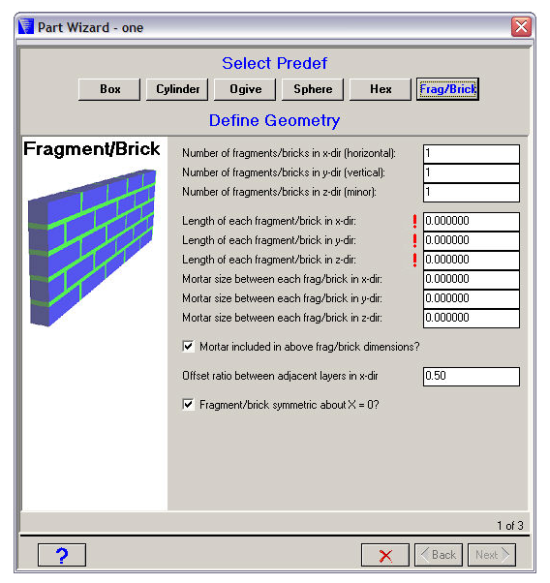
The fragment/brick wall is built with its axes parallel to the X, Y, and Z axes.
The X direction runs the length of the wall.
The Y direction runs the height of the wall.
The Z direction runs through the thickness of the wall.
- Number of fragments/bricks
The number of fragments/bricks in the X, Y, and Z directions.
- Length of each fragment/brick
The length of a single brick/fragment in the X, Y, and Z directions.
- Mortar size between each fragment/brick
The mortar size (or gap) between fragments/bricks.
- Mortar included in dimension?
Check this box if you want the mortar size to be included in the length of each brick/fragment.
- Offset ratio
The offset ratio for the fragments/bricks.
This is how the bricks are staggered along the length of the wall. For example, if the offset is 0.5 (the default), the bricks will be staggered halfway across each other as shown in the above figure.
- Fragment/brick symmetric about X=0?
Check this box if you want the wall to be symmetric about X=0.
Enter the required dimensions for your predef and click  to advance to the next dialog window (Define Zoning).