


The Mesh Data object contains settings that affect the mesh
globally.
The blade-specific mesh data objects contain a subset of the settings
of the Mesh Data object, and affect the mesh for individual
blades in the blade set.
The complex blade end Mesh Data objects affect the mesh for individual complex blade ends.
The following topics are discussed:
The Mesh Size tab is applicable to the Mesh
Data object.
In some situations, for example when you are comparing minor geometry variations, you may want to keep the mesh dimensions the same from one case to the next. This will reduce the influence of the mesh on the CFD results. To lock the mesh dimensions, select the Lock mesh size check box. This setting will maintain the current mesh dimensions and prevent any subsequent changes to the global or local mesh controls. The lock status will be preserved from one session to the next if the project or state file is saved. To unlock the mesh, clear the Lock mesh size check box.
The Method setting controls the mesh density, and can be set to one of the following:
Target Passage Mesh SizeThe
Target Passage Mesh Sizemethod sets a target for the number of nodes in the mesh passage. The pre-set options for the Node Count setting areCoarse (20000),Medium (100000), andFine (250000). There is also an option,Specify, to specify the target number of nodes. In this mode, if you change the spanwise mesh size or the boundary layer refinement, or make any local refinements to the mesh, Ansys TurboGrid will adjust the mesh size factor (Global Size Factor) automatically to achieve the desired target mesh size.Ansys TurboGrid attempts to reach the target number of nodes by:
Adjusting the number of elements placed along each topology block edge. The number of elements can be viewed after pressing Apply by changing the method to
Global Size Factor.Adjusting the number of elements from hub (or hub tip) to shroud (or shroud tip) if these have not been explicitly set.
Global Size FactorThe
Global Size Factormethod defines the overall mesh size. To increase the resolution of the mesh, increase the size factor using the Size Factor setting. Note that the change in overall mesh size is not linear. In this mode, if you change the spanwise mesh size or the boundary layer refinement, or make any local edge refinements to the mesh, the Global Size Factor will stay fixed and the overall mesh size may change. This factor, when used with proportional refinement, can be used to scale the mesh size for a mesh refinement study.
In the context of the Boundary Layer Refinement Control settings, the boundary layer region is represented by:
The blade boundary layer region, which is the set of topology blocks along the sides of the blade, plus
The mesh near the hub and shroud.
The blade boundary layer region varies in thickness (outward from the blade) around the blade profile, as indicated by distances A and B in Figure 10.14: Variations in boundary layer region thickness.

Within the blade boundary layer region, TurboGrid uses various expansion rates to distribute the elements normal to the blade surface to assure a smooth transition to the passage mesh.
The blade boundary layer region thickness is a function of the variables shown in Figure 10.15: Variables that control the blade boundary layer region distribution.
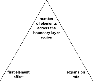
The number of elements outward across the blade boundary layer region is constant around the blade profile. Because the blade boundary layer region thickness (see Figure 10.14: Variations in boundary layer region thickness) changes around the blade, either the expansion rate or the first element offset (that is, the height of the first row of elements next to the blade) can be constant, but the other must change.
You can specify which properties of the boundary layer region to control by using the Boundary Layer Refinement Control > Method setting. The options are:
Proportional to Mesh SizeThis option controls the number of elements outward across the blade boundary layer region in proportion to the values specified for Factor Base and Factor Ratio. This method maintains similar expansion rates when the Global Size Factor is changed. If the blade has a cut-off edge, Factor Ratio also controls the number of elements along the cut-off edge.
Increasing the value of Factor Base or Factor Ratio increases the number of elements outward across the blade boundary layer region and along the cut-off edge (if applicable). Conversely, decreasing the value of Factor Base or Factor Ratio decreases the number of elements. The number of elements outward across the blade boundary layer region is calculated as Base Count * Global Size Factor * (Factor Base + Factor Ratio * Global Size Factor). The default values of Factor Base and Factor Ratio are 3 and 0 respectively.
First Element OffsetThis option directly controls the height of the first row of elements next to the blade.
First Element Offset and Element CountThis option controls the height of the first row of elements next to the blade, hub, and shroud, via parameter Offset and the number of elements outward across the blade boundary layer region via parameter Count.
When using the
First Element Offset and Element Countoption, Target Maximum Expansion Rate (described in Target Maximum Expansion Rate) is not applicable.Edge Refinement FactorThis factor is multiplied with Base Count * Global Size Factor to determine the number of elements outward across the blade boundary layer region.
When Constant First Element Offset is selected, you can influence the range of expansion rates using the Target Maximum Expansion Rate settings, described in Target Maximum Expansion Rate.
When the topology is created, Ansys TurboGrid creates a Boundary Layer
Control object under the Mesh Data
object in the object selector. The Boundary Layer
Control object shows information about the boundary
layer.
Note:
When Boundary Layer Refinement Control > Method option is set to
First Element Offset, the offset value can be controlled either in theBoundary Layer Controlobject or the Mesh Data > Mesh Size tab.When Boundary Layer Refinement Control > Method option is set to
First Element Offset and Element Count, the offset and count values can be controlled either in theBoundary Layer Controlobject or the Mesh Data > Mesh Size tab.
When Constant First Element Offset is selected,
TurboGrid uses a double-sided node distribution (a non-constant expansion rate)
for the boundary layer.
In this case, the near-wall expansion rates that are
reported in the Boundary Layer
Control object indicate the
approximate minimum and maximum values based on a sample of the layer values.
When Constant First Element Offset is not selected, TurboGrid uses a single sided node distribution for the boundary layer; at any given position around the blade (in the blade-to-blade view), there is a constant expansion rate across the boundary layer. In this case, the user-specified first element offset is applied approximately as an average offset.
Note: Mesh element aspect ratios (spanwise length to wall offset length) on the blade surface at the leading and trailing edges might be higher with Constant First Element Offset not selected compared to with Constant First Element Offset selected. With ATM3D, you can reduce these aspect ratios by increasing the spanwise mesh resolution or by increasing the boundary layer first element offset. If you see solver convergence issues related to high aspect ratios, try running a double precision solver.
The Cutoff Edge To Boundary Layer setting is available only for cut-off blades.
You can adjust Cutoff Edge To Boundary Layer > Factor to change the expansion rate used near the cut-off edge.
The Cutoff Edge Split Factor setting is available only for cut-off blades.
In cases where the leading edge and/or trailing edge is cut-off, you can specify a factor for each cut-off edge to control the number of elements along that edge (as viewed in any given layer).
The Target Maximum Expansion Rate setting is available only when Constant First Element Offset is selected.
Selecting Target Maximum Expansion Rate enables the specification of a target maximum expansion rate. TurboGrid attempts to prevent the expansion rate (at any place around the blade profile) from exceeding the specified maximum in different ways, depending on the Boundary Layer Refinement Control > Method option:
Proportional to Mesh SizeThe number of elements across the boundary layer is fixed. TurboGrid may increase the first element offset in order to reduce the maximum expansion rate as appropriate.
First Element OffsetThe first element offset is fixed. TurboGrid may increase the number of elements across the boundary layer in order to reduce the maximum expansion rate as appropriate.
Note: Target Maximum Expansion Rate is available only when Constant First Element Offset is selected.
If reducing the maximum expansion rate to the specified maximum results in a sub-unity expansion rate (that is, a contraction rate) elsewhere, specifically such that the expansion rate is, at some place, less than the inverse of the specified maximum, then TurboGrid may balance the amounts by which:
The maximum expansion rate is above the maximum
The minimum expansion rate is below the inverse of the maximum
If the balance involves exceeding the rate by more than 15%, the
problem will be indicated in the Boundary Layer
Control object (which is under the Mesh
Data object in the object selector).
The Near Wall Element Size Specification setting controls the method by which the near-wall node spacing is specified on the Passage and Hub/Shroud Tip tabs. The near-wall node spacing is the distance between a wall (for example, hub, shroud, or blade) and the first layer of nodes from the wall.
The available Method options for calculating the near wall spacing are:
The  method allows you to set the near wall spacing,
 , in accordance with a target value of
 . The target value of
  may then be specified on the
Passage and Hub/Shroud
Tip tabs, as applicable (that is, when a near wall
size is required by the specified distribution method).
may then be specified on the
Passage and Hub/Shroud
Tip tabs, as applicable (that is, when a near wall
size is required by the specified distribution method).
The following formula relates the near wall spacing to
 :
:
 | (10–1) |
where  is the blade chord,
  is the specified target
  value,
  is the Reynolds number based on the distance along
the chord (measured from the leading edge), and
is the Reynolds number based on the distance along
the chord (measured from the leading edge), and  is the Reynolds number based on chord length.
Ansys TurboGrid approximates
is the Reynolds number based on chord length.
Ansys TurboGrid approximates  as the algebraic average of the chord lengths of
each blade profile in the blade file. You must specify
as the algebraic average of the chord lengths of
each blade profile in the blade file. You must specify
 . Ansys TurboGrid approximates
  as being equal to the specified value of
 .
.
Note: If you specify a near wall size (on the
Passage or Hub/Shroud
Tip tab) when the near wall method is not
 , you can switch the method to
  (at least temporarily) to see the estimated
value of
(at least temporarily) to see the estimated
value of  as a setting on the
Passage or Hub/Shroud
Tip tab.
as a setting on the
Passage or Hub/Shroud
Tip tab.
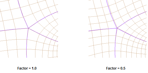
An ATM-based mesh may contain one or more vertices that each join exactly five edges. At these locations, the mesh generation process will tend to pull the mesh away from the five-edge vertex to make the surrounding element edges more orthogonal, resulting in relatively larger elements surrounding the vertex than the rest of the mesh in their vicinity. The Five-Edge Vertex Mesh Size Reduction > Factor setting, when set to a value less than 1.0, will reduce this tendency, trading off between mesh orthogonality for sizing.
The Passage tab is applicable to the Mesh
Data object, and is used to specify distribution settings.
Distribution settings are described generically in Distribution Settings in General.
Use the Spanwise Blade Distribution Parameters section to control the distribution of mesh elements in the spanwise direction along the blade.
The Method setting and its associated settings are described in Distribution Settings in General.
The Hub Tip and Shroud Tip tabs of
the Mesh Data object are available when their respective
geometry objects (Hub Tip and Shroud Tip) exist.
For details on defining those geometry objects, see The Hub Tip and Shroud Tip Objects.
If you have defined any complex blade ends (see Meshing High-Fidelity Geometry),
the respective tabs of the Mesh Data object are renamed;
if there is a complex blade end at the hub, the Hub Tip
tab becomes the Hub Complex Blade End tab;
if there is a complex blade end at the shroud, the Shroud Tip
tab becomes the Shroud Complex Blade End tab. The available
settings vary by tab.
Setting descriptions follow:
Use these settings to control the distribution of mesh elements in the spanwise direction across the tip gap.
Set Method to one of the following:
Match Expansion at Blade TipElement Count and SizeUniform
These methods are described in Distribution Settings in General.
The settings under Blade Tip (for cases with a single blade per blade set) or Apply Blade Tip Parameters To All Blades (for cases with multiple blades per blade set) control details of the mesh elements on the blade tip (and throughout the blade tip region of the mesh).
The settings that are available depend on the type of leading edge and the type of trailing edge:
The first element height in the tip mesh is matched with the first element height in the boundary layer region (outside the blade). The match may not be exact in rounded leading edge or trailing edge regions.
In the tip mesh, the mesh elements change height across the blade thickness according to locally applied near-wall expansion rates. These expansion rates are limited at the thickest part of the blade by a target maximum rate, which is determined by the first applicable method of the following methods:
If you select Override Target Maximum Expansion Rate, the corresponding specified rate is used.
If you select Target Maximum Expansion Rate (on the Mesh Size tab), the corresponding specified rate is used.
The maximum achieved expansion rate in the boundary layer region (outside the blade) is used.
The expansion rate influences the number of mesh elements across the blade tip.
After the topology has been generated, TurboGrid reports the minimum and maximum achieved expansion rates, and the number of mesh elements across the blade tip, in the Hub Tip and Shroud Tip tabs.
The distribution of elements across the blade tip mesh is governed by the distribution of elements across the cut-off edge. The latter is controlled indirectly by the Cutoff Edge Split Factor setting (on the Mesh Size tab) which controls the number of elements across the cut-off edge. For details, see Cutoff Edge Split Factor.
The Tip Centerline Location setting is available when the following conditions are met:
The corresponding blade tip, hub or shroud, exists.
The tip topology is set to
H-Grid Not Matching.The corresponding edge of the blade, leading or trailing, is cut-off.
The setting controls how the blade centerline behaves at the cut-off end. The options are:
AutomaticEffectively selects one of the other two methods automatically, based on the geometry. If one of the corners of the cut-off edge is at a sufficiently acute angle (default is 45°), then the
Corneroption is selected, otherwise theMiddleoption is selected. The threshold angle can be set by defining the parameterGGI Tip Angle To Switch Mean Line Into Cut Off Corner(to an angular value; default unit is[degree]) in the CCL for the blade-specific mesh data object.MiddleThe centerline meets the cut-off blade edge in the middle (between the corners).
CornerThe centerline meets the corner of the cut-off blade edge.
Use these settings to control the distribution of mesh elements near the complex blade end.
The Spanwise Element Count settings affect the number of hex elements placed spanwise across the complex blade end clearance gap.
Method can be set to:
Element CountSet Number of Edge Splits to the number of hex elements to place spanwise across the complex blade end clearance gap
Factor(the default for new cases)Set Element Count Factor to a value that multiplies with a computed suggested number of edge splits to yield the target number of edge splits.
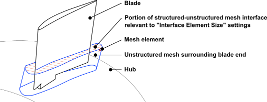
The Interface Element Size settings control the element size over the interface between the structured hex mesh of the passage and the unstructured mesh block for the complex blade end.
Method can be set to:
SizeSet Normalized Interface Element Size to the target element size over the interface between the structured hex mesh of the passage and the unstructured mesh block for the complex blade end.
Size Factor(the default for new cases)Set Element Size Factor to a value that multiplies with a computed suggested normalized interface element size to yield the normalized interface element size.
The default interface element size aims to make isotropic the mesh element in the position shown in the illustration below.
Note: If the span varies significantly from leading to trailing edge, generation of the unstructured mesh might benefit from changes to:
The interface element size, and
The interface span position, which is controlled by the Span Location setting on the Complex Blade End tab for the applicable complex blade end
Mesh
                        Data
object. For details, see Setting Descriptions for Complex Blade End Mesh Data Objects.
The distribution of elements along the blade (in the spanwise direction) is controlled by one of these methods:
Element Count and SizeTo use the
Element Count and Sizemethod, specify the number of elements that span the pertinent extent and whether the distribution is uniform or non-uniform. If the distribution is non-uniform, you must also specify the number of uniformly-distributed elements (Const Elements) and the element s ize next to the pertinent wall(s).Boundary LayerTo use the
Boundary Layermethod (not applicable for O-Grid settings), specify distribution parameters for three sections: boundary layer at the hub, boundary layer at the tip/shroud, and the section in between. Layer Offset means the thickness of the boundary layer and Wall Offset means the thickness of the first element next to the wall.Expansion RateTo use the
Expansion Ratemethod, specify an expansion rate and the element size next to the blade wall.UniformTo use the
Uniformmethod, specify the number of elements. Each element is the same size.Proportional(the only option when using a meridional splitter)This is the default method when ATM topology is used. With this method, Ansys TurboGrid automatically computes the number and distribution of elements in the spanwise direction so that the near wall element heights on the hub and shroud match the maximum near wall element height on the blade. Ansys TurboGrid adjusts the spanwise node count in proportion to the blade aspect ratio, the square root of the streamwise node count, and the proportional Factor. Increasing the proportional Factor increases the mesh resolution in the spanwise direction.
When there is a meridional splitter, the Passage Boundary Layer Refinement Control > Factor setting is available, and scales the near wall element heights on the hub, meridional splitter, and shroud surfaces.
Note: The Const Elements value cannot be negative and must be at least 2 less than the # of Elements value for that region.
The distribution of elements across a tip gap (in the spanwise direction) is controlled by one of these methods:
Match Expansion at Blade TipThe
Match Expansion at Blade Tipmethod is default. This method will apply the same expansion factor as that used along the blade span, and will match the size of the elements on each side of the tip clearance gap with the size of the first element along the blade. An appropriate number of elements is then derived.Element Count and Size(described above)
Uniform(described above)
When using the End Ratio method, the element count and
wall size(s) are updated accordingly in the Element Count and
Size settings. (When two wall sizes are adjusted, they are
adjusted to the same value.) When using the Element Count and
Size method, the End Ratio setting is
updated accordingly.
In the case of an O-Grid distribution, the Blade End
Ratio is the size ratio of the passage mesh element nearest the
O-Grid to the O-Grid element nearest the blade surface. A special feature of the
distribution settings for O-Grids is that, if # of
Elements is set to 0, the number of elements
will be calculated automatically so that the best possible matching of element
sizes at the interface between the O-Grid and the passage is ensured.
Size of Elements Next to Wall (Normalized) is normalized
based on the total distance along the blade (not counting any tip clearance
gaps). For example, on the Hub Tip tab, a value of
0.05 for Size of Elements Next to Wall
(Normalized) > Hub represents an element
size of five percent of the distance along the blade, applied on the elements
next to the hub, and a value of 0.05 for the Size of Elements Next to
Wall (Normalized) > Tip represents an
element size of five percent of the distance along the blade, applied on the
elements next to the hub end of the blade (both in the tip clearance gap and on
the blade).
Note: The Size of Elements Next to Wall (Normalized) value must be less than 1 (unity) divided by the number of elements for that region. If it is not, Ansys TurboGrid decreases it to meet this criterion.
To increase the quality of the mesh, try to minimize drastic changes in element size. Wherever possible, attempt to have gradual increases and decreases in element size in all directions.
The geometries of the inlet and outlet domains of the mesh are controlled by
the hub and shroud curves, and the Inlet and
Outlet geometry objects. For details, see The Hub and Shroud Objects and The Inlet and Outlet Objects.
The Inlet/Outlet tab contains settings, as
applicable, that affect the mesh in the inlet and outlet domains. The
Inlet Domain and Outlet domain
check boxes on the Mesh Size tab of the Mesh
Data object determine whether or not the inlet and outlet domains
are to be generated as part of the mesh.
The nodes of the inlet and outlet domains match one-to-one with the nodes of the passage domain where they meet at the interfaces. The rest of the mesh in the inlet or outlet domain is then as near to being isotropic and orthogonal as possible.
Mesh Type can be set to one of the following options:
H-Grid(default)If you have any hub and/or shroud regions defined (see Hub Regions and Shroud Regions Tab), and the applicable domain (Inlet Domain or Outlet Domain) is selected on the Mesh Size tab, then setting Mesh Type to
H-Gridmakes available the Limit Aspect Ratio and Inlet Multi Segment Enabled/Outlet Multi Segment Enabled settings (described below).H-Grid in Parametric SpaceIn this case, the resulting mesh tries to follow a parametric space created by an elliptic smoothing method. This type of mesh is particularly suitable for return channels.
Both options specify an H-Grid type mesh in the inlet/outlet domain that preserves the boundary layer mesh resolution at the hub and shroud and automatically matches the element size at the interface between the inlet/outlet domain and passage domain.
The streamwise distribution of elements is non-uniform and uses a constant expansion rate.
Define By can be set to one of the following options:
Target Expansion Rate(default)In this case, the number of elements in the inlet/outlet domain is determined by matching the element size at the passage interface and expanding the size at a prescribed rate for each successive element. The default expansion rate (element size ratio) is 1.2
Target Number of ElementsThe # of Elements setting controls the target number of elements in the inlet/outlet domain in the streamwise direction. The expansion rate is determined by the target number of elements, the streamwise length of the inlet/outlet domain, and the passage element size.
Important: Clicking the Apply button does not create the
mesh, it only saves the Mesh Data object and
updates the 2D mesh previews. To create the mesh, select
Insert > Mesh from the
main menu or click Create Mesh
 .
.
If you have any hub and/or shroud regions defined (see Hub Regions and Shroud Regions Tab),
and the applicable domain (Inlet Domain or Outlet Domain) is selected on the Mesh Size tab,
and Mesh Type is set to H-Grid,
then the Limit Aspect Ratio option is available.
The Limit Aspect Ratio option enables you to specify a maximum target aspect ratio for mesh elements in the inlet/outlet domain by setting a value for Request Max AR value.
TurboGrid may increase the element count in the streamwise direction in an attempt to reduce the maximum aspect ratio to (or below) the target value. The existing maximum aspect ratio is shown in the object editor beside the label Current Max AR.
Note that the number of elements in the spanwise direction is controlled by the passage mesh.
If you have any hub and/or shroud regions defined (see Hub Regions and Shroud Regions Tab),
and the applicable domain (Inlet Domain or Outlet Domain) is selected on the Mesh Size tab,
and Mesh Type is set to H-Grid,
then the Inlet Multi Segment Enabled/Outlet Multi Segment Enabled option is available,
and is selected by default. When this option is selected:
Any defined hub/shroud regions are enabled (affecting the mesh and surface regions in the output), and
Settings for controlling the mesh distribution within the hub/shroud regions become available.
If you select a segment (a defined hub/shroud region or a numbered surface region that is beside a defined hub/shroud region) in the list, the segment is highlighted in the 3D Viewer and you can then change the resolution via the Resolution in Segment setting. The specified value directly scales the number of elements (# Elements) along the segment (in the streamwise direction). Note that the minimum number of elements along any segment is 4.
The Segment Boundary Size Factor setting directly scales the element thickness (as measured in the streamwise direction) on all segment boundaries except the outermost segment boundaries. Note that this setting indirectly affects the number of elements along each and every segment.
Figure 10.16: Inlet Domain Segments shows an example of a 3D Mesh object with 2D regions that correspond with the segments inside the inlet domain.
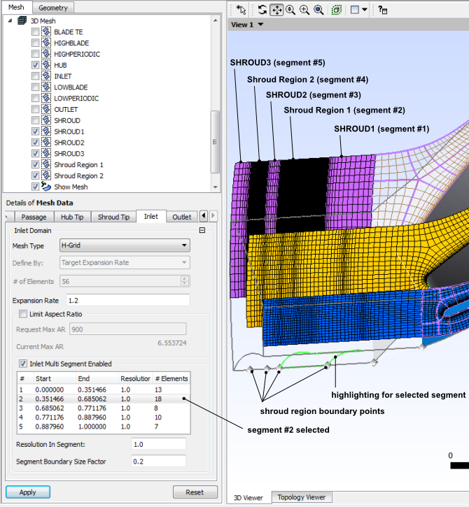
In this example, there are:
Two defined shroud regions in the inlet domain: "Shroud Region 1" and "Shroud Region 2". These regions can be renamed and otherwise redefined in the
Shroudgeometry object settings.Three other regions on the shroud in the inlet domain: "SHROUD1", "SHROUD2", and "SHROUD3". These regions are automatically generated in order to cover the rest of the shroud within the inlet domain.
No defined hub regions. (Hub regions could potentially be added.)
The Mesh Around Blade tab is applicable to the blade-specific mesh data objects.
The Size of Elements Next to Wall (Normalized) setting is described in Distribution Settings in General.
The Hub Tip, and Shroud Tip settings
are for controlling the number of elements across the hub tip gap or shroud tip
gap. They are similar to the settings on the Hub Tip and
Shroud Tip tabs for the Mesh Data
object. For details, see Hub Tip/Complex Blade End and Shroud Tip/Complex Blade End Tabs.
For details, see Blades with two cut-off edges.