The ATM method supports the following tandem vane templates:
Table 10.3: Tandem Vane Templates
|
Template Name |
Description |
|---|---|
|
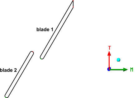
TandemVaneAlignedHigh TandemVaneAlignedLow |
The leading edge of the second blade is positioned, in the meridional direction, near or behind the trailing edge of the first blade. The second blade should be offset by approximately half a blade pitch (in the theta direction) compared to the first blade. The leading and trailing edges of the first blade and second blade are rounded. You must choose one of the two templates. For details, see Choosing the Appropriate TandemVaneAligned Template. |
|
TandemVanesCustomizedNr1 |
The leading edge of the first blade is positioned, in the meridional direction, near or behind the trailing edge of the second blade. The leading edge of the first blade is positioned at a lower Theta value than the trailing edge of the second blade. The leading edge of the first blade is rounded. The trailing edge of the first blade is cut-off. The leading and trailing edges of the second blade are rounded. For details, see The TandemVanesCustomizedNr1 Template. |
To access these templates, enable advanced features. For details, see Advanced Topology Control.
The tandem vane template has a "Low" and "High" version. To determine which tandem vane template is appropriate:
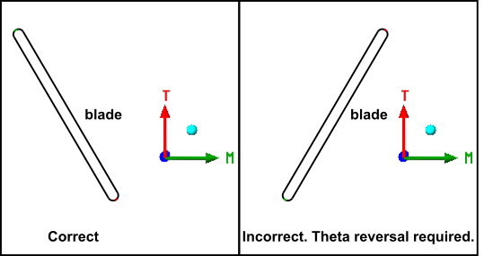
Right-click in the viewer and select Transformation > 3D Turbo (Theta-M’-Span).
Orient the view so that the meridional coordinate (M) increases to the right and Theta (T) increases upward.
After you do this, the leading edges are on the left.
Proceed to the next step if Theta decreases towards the trailing edge (towards higher meridional coordinate). Otherwise, use the settings under Geometry > Machine Data > Rotation to reverse the direction of increasing Theta in relation to the geometry.
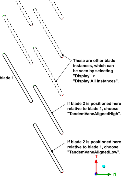
If Theta increases from the first blade’s trailing edge to the second blade’s leading edge, select
TandemVaneAlignedHigh. Otherwise, selectTandemVaneAlignedLow.
Note: When running TurboGrid in stand-alone mode (as described in Using the Ansys TurboGrid Launcher in the TurboGrid Introduction), it is possible to rotate the second blade along the Theta direction, which can potentially change which template is suitable, as determined by the procedure above.