


A plane locator is a two-dimensional area that exists only within the boundaries of the geometry. To create a new plane, select Insert > User Defined > Plane from the main menu.
The available methods for defining a plane are described next:
YZ PlaneCreate a plane normal to the X axis and at a specific X value. Type in a value for X, set it using the embedded slider, or click in the box beside X, then click Enter Expression
 to the right of the
X setting and enter its value as an
expression. For details, see Expressions Command.
to the right of the
X setting and enter its value as an
expression. For details, see Expressions Command.ZX PlaneCreate a plane normal to the Y axis and at a specific Y value. Type in a value for Y, set it using the embedded slider, or click in the box beside Y, then click Enter Expression
to the right of the
Y setting and enter its value as an
expression. For details, see Expressions Command.XY PlaneCreate a plane normal to the Z axis and at a specific Z value. Type in a value for Z, set it using the embedded slider, or click in the box beside Z, then click Enter Expression
to the right of the
Z setting and enter its value as an
expression. For details, see Expressions Command.Point and NormalCreate a plane using a single point on the plane and a vector normal to the plane.
To set the point coordinates, first click one of the point coordinate boxes. The point coordinates will be displayed with a yellow background and the viewer will switch to picking mode. You can then pick a point directly by clicking a visible object in the viewer. The point can lie outside of the domain.
You can alternatively set the coordinates one at a time by typing in the coordinates and/or using the embedded slider that appears beneath the coordinate boxes.
When picking a point from the viewer for the normal vector, the vector is taken from the origin to the point picked.
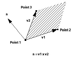
Three PointsCreate a plane using three points. To set the point coordinates, first click one of the point coordinate boxes. The point coordinates will be displayed with a yellow background, and the viewer will switch to picking mode. You can then pick a point directly by clicking a visible object in the viewer. The point can lie outside of the domain.
You can alternatively set the coordinates one at a time by typing in the coordinates and/or using the embedded slider that appears beneath the coordinate boxes.
The normal vector to the plane is calculated using the right-hand rule. The first vector is from Point 1 to Point 2 and the second is from Point 1 to Point 3 as shown in the diagram below.
The available types of bounds are described next:
When
Noneis selected the plane cuts through a complete cross-section of each domain specified in the Domains list. The plane is only bounded by the limits of the domains.The
Circularoption defines the bounds of a plane as a circle centered at the point used in the Plane Definition. Enter the value of the radius of the circle or click in the box beside Radius, then click Enter Expression to the right of the Radius
setting to enter an expression for the radius of the circle. The
plane is undefined in areas where the circle extends outside of the
domains specified in the Domains list.For the
Rectangularoption, the plane bounds are defined by a rectangle centered about the point selected in the Plane Definition with lengths in the x and y-directions of X Size and Y Size, respectively. You may have to specify lengths in other directions, depending on the Plane Definition. The size is determined with reference to the plane center (that is, the plane is resized around its center). The X Angle value rotates the plane counter-clockwise about its normal by the specified number of degrees. The plane is undefined in areas where the rectangle extends outside of the domains specified in the Domains list.
Both the circular and rectangular options have an Invert Plane Bound check box. If this check box is selected, the area defined by the rectangle or circle is used as a cut-out area from a slice plane that is bounded only by the domain(s). The area inside the bounds of the rectangle or circle does not form part of the plane, but everything on the slice plane outside of these bounds is included.
Set Plane Type to either Slice or Sample.
Slice extends the plane in all directions until it reaches the edge of the domain. Points on the plane correspond to points where the plane intersects an edge of the mesh. As a result, the number of points in a slice plane is indirectly proportional to the mesh spacing.
Sample creates the plane with either
circular or rectangular bounds, depending on the plane bounds selected. For
the Circular option, the density of points on the plane
corresponds to the radius of the plane specified in the Plane
Bounds frame, and the values for the
Radial and Circumferential
settings in the Plane Type frame. For rectangular
bounds, the density of points on the plane corresponds to the size of the
bounds for the plane in each of the plane directions, and the sample values
provided in the Plane Type frame. A sample plane is a
set of evenly-spaced points that are independent of the mesh spacing.
Picking Mode can be used to select and/or translate planes in the viewer. For details, see Viewer Toolbar.
See Color Tab for details.
See Render Tab for details.