Review displacement results as described in the following sections:
Review the Weighted Average values recorded for the displacement transfer in the final coupling iteration to verify that the displacements sent by Mechanical match those received by CFX.
Figure 51: Displacement reported in the Transcript at Coupling Step 100, Iteration 5
+=============================================================================+
| COUPLING STEP = 100                       SIMULATION TIME = 1.00000E+01 [s] |
+-----------------------------------------------------------------------------+
|                                     |      Source            Target         |
+-----------------------------------------------------------------------------+

...

+-----------------------------------------------------------------------------+
|                           COUPLING ITERATION = 5                            |

...

+-----------------------------------------------------------------------------+
| CFX                                 |                                       |
|   Interface: CouplingInterface 1    |                                       |
|     Mesh_Displacement               |             Converged                 |
|       RMS Change                    |     1.83E-06          1.79E-06        |
|       Weighted Average x            |    -1.36E-02         -1.36E-02        |
|       Weighted Average y            |    -3.34E-04         -3.32E-04        |
|       Weighted Average z            |    -1.80E-11         -1.84E-11        |
+-----------------------------------------------------------------------------+
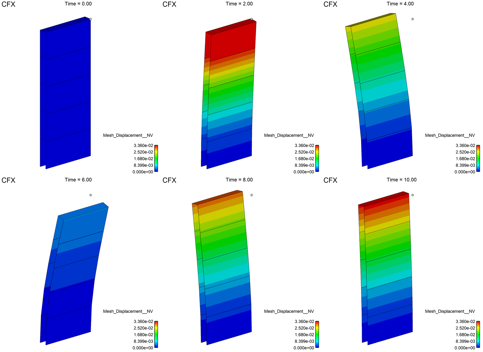
Visualize the application of Mechanical-generated incremental displacements to CFX's solid region. Note that the fluid region cannot be shown in EnSight, but you can view the effects of the displacements on CFX's solid plate body.
Perform the following steps:
Apply the Mesh_Displacement__NV variable to CFX's target region.
The animation shows the incremental displacements on the target side of the plate body for each time step of the co-simulation. The interactive probe serves as the reference point for the motion of the valve.
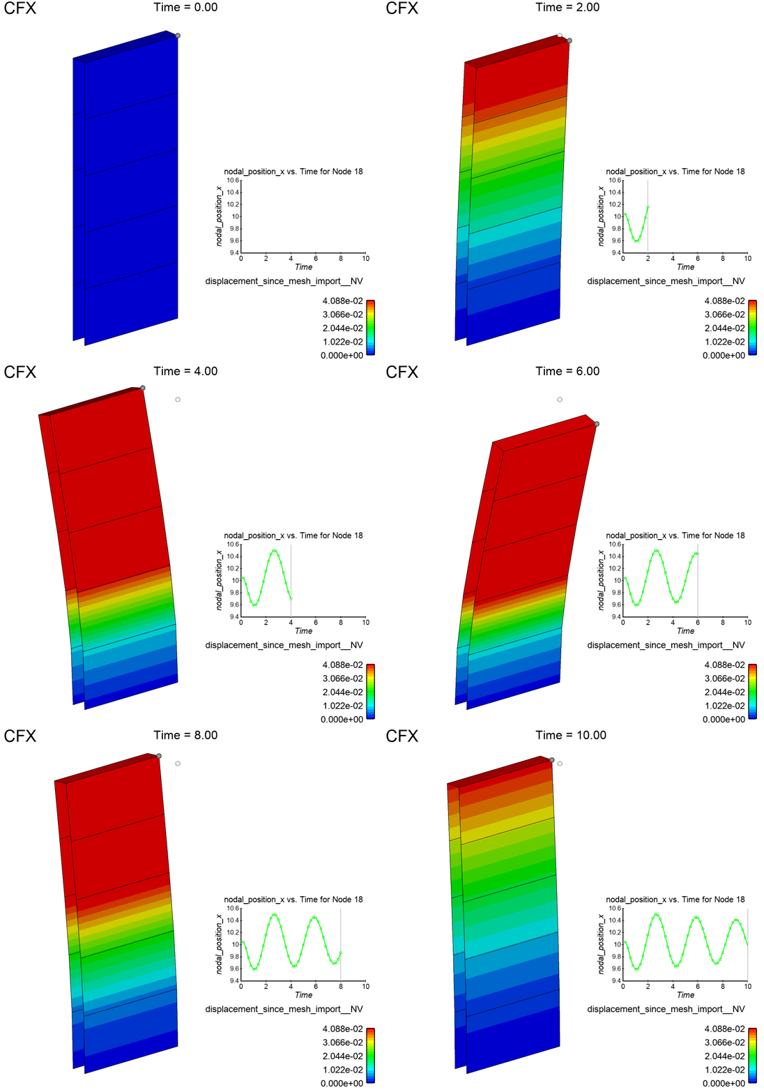
Visualize the total nodal displacement as a function of time on CFX's solid reed valve body.
Perform the following steps:
Apply the displacement_since_mesh_import__NV variable to CFX's target region.
Note: You may use the interactive probe and time annotation created in the previous section.
The animation shows the total displacement on the target side of the plate over the duration of the co-simulation.


