Ensure that the losses generated by Maxwell are the same as those consumed by the Mechanical. To verify the application of losses, check System Coupling's Transcript and EnSight-formatted Results files, as described in the following sections:
Review the Sum values for the final coupling iteration to verify that the losses sent by Maxwell match those received by Mechanical.
Figure 24: Losses reported in the Transcript at Coupling Step 1, Iteration 5
+=============================================================================+
| COUPLING STEP = 1                                                           |
+=============================================================================+

+=============================================================================+
|                             COUPLING ITERATIONS                             |
+-----------------------------------------------------------------------------+
|                                     |      Source            Target         |
+-----------------------------------------------------------------------------+

...

+-----------------------------------------------------------------------------+
|                           COUPLING ITERATION = 5                            |
+-----------------------------------------------------------------------------+

...

+-----------------------------------------------------------------------------+
| MAPDL Steady-State Thermal          |                                       |
|   Interface: CouplingInterface 1    |                                       |
|     Loss 1                          |             Converged                 |
|       RMS Change                    |     6.96E-04          8.45E-04        |
|       Sum                           |     1.18E+03          1.18E+03        |
|   Interface: CouplingInterface 2    |                                       |
|     Loss 2                          |             Converged                 |
|       RMS Change                    |     8.94E-04          9.37E-04        |
|       Sum                           |     9.62E+02          9.62E+02        |
|   Interface: CouplingInterface 3    |                                       |
|     Loss 3                          |             Converged                 |
|       RMS Change                    |     8.73E-04          1.03E-03        |
|       Sum                           |     1.17E+03          1.17E+03        |
+-----------------------------------------------------------------------------+
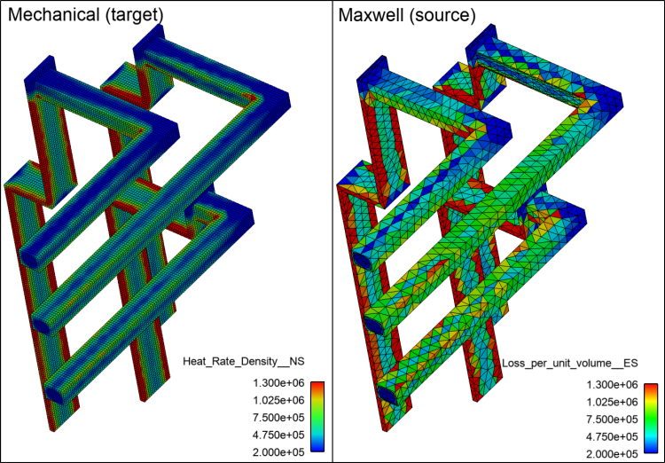
In EnSight, visualize the application of Maxwell-generated losses to Mechanical's thermal analysis. Use the following variables:
Mechanical (nodes): Heat_Rate_Density__NS
Maxwell (elements): Loss_per_unit_volume__ES
For consistency, adjust the palette ranges as shown in the image below.