


Spot Weld Tool
The Spot Weld tool creates points on two faces that represent weld points. Each spot weld consists of two points: one on each face that is to be welded together. Each point must lie on a face or edge. For export to Ansys, each point must lie on a different solid or surface part.
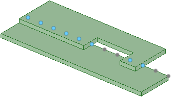
When spot weld points are found on another body, the set does not include points with mates within the same body, as shown below. Weld points in a set that have mates are blue and points that do not have mates are gray.
Spot welds are updated with changes to the guiding edges or base faces.
If a guiding edge disappears, the points created along it are removed.
If a mate face moves out of the search range the weld point, the pairs to that mate face will disappear.
If the mate face moves back into the range, the point pairs will reappear.
If pairs cannot be found for all of the points on the base face, the spot weld is marked in the Structure tree with an error icon showing that it is no longer valid.
Dimensions for spot weld point patterns are displayed in the Design window. These dimensions look the same as dimensions for other patterns.