


Midsurface Tool
The Midsurface tool creates a surface midway between two offset faces. The midsurfaces are automatically extended or trimmed to adjacent faces, and the distance between the original faces is stored as a thickness property. You can use these midsurfaces for FE analysis.
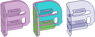
Color highlighting shows you face pairs that have been selected, as shown below. The midsurface will be offset from the cyan faces. Green indicates that a face is paired with a cyan face. Unselected faces and faces without offsets are shown in the original color.
The thickness of the original model face offsets are stored as a property named Thickness in the Midsurface section of the Properties panel. This is a face property, so you must select the face in the Design window rather than in the structure tree, even if it is a single face. You can change this property, and it is included in the Ansys data when it is sent out to Ansys via the SpaceClaim add-in.
The Midsurface tool detects and removes small faces of midsurfaces that are created when an edge is equal to half of the part thickness.
If the Midsurface tool finds missing faces because neither side can be offset, you will receive an error message in the error box that lists the faces. If the tool fails to create midsurface parts, the problem faces or edges are highlighted.
- Midsurfaces inherit the material properties of their parent components, but you can change the material properties for the midsurface object.
- Midsurfaces are shown in the structure tree with a default name that includes the assigned thickness. When you rename the surface, the thickness is appended to the new name.
- You can change the thickness of a midsurface face, select the midsurface face in the Design window and change the Thickness property in the Properties panel.
- You can remove the Midsurface association by setting the Thickness to 0.
- When you right-click a Midsurface in the tree, you can select the source body using .