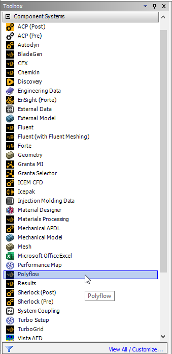
Similarly, you can create a Polyflow-based component system in Workbench by double-clicking Polyflow under Component Systems.
Important: You can also create a Polyflow component system by left-clicking Polyflow under Component Systems in the Toolbox, and then dragging it onto the Project Schematic.
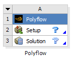
The new Polyflow component system appears in the Project Schematic as a box containing two cells: the Setup cell and the Solution cell (Figure 1.5: A Polyflow Component System). The Setup and Solution cells in a Polyflow component system work in similar manner to the description provided previously for the Fluid Flow (Polyflow) analysis system. Note that the mesh must originate from a file imported into the Setup cell, or it must be provided through a connection from an upstream system. You must also connect the Polyflow component system to a Results component system if you want to postprocess the results using Ansys CFD-Post.