Ansys Polyflow’s volume of fluid method tracks a liquid fluid on a domain
 . A material property variable
  represents the fluid fraction.
 is used to identify where the fluid is present, and is governed by the
following transport equation:
is used to identify where the fluid is present, and is governed by the
following transport equation:
 | (21–1) |
where  represents the velocity of the fluid. Note that the values for
 that result from solving the previous equation are highly
discontinuous, and hence difficult to simulate.
that result from solving the previous equation are highly
discontinuous, and hence difficult to simulate.
Equation 21–1 is governed by initial and inlet conditions:
initial conditions
You must define the
 variable for the domain at the initial time, in order to
specify where fluid is initially present and not present. This necessarily
introduces discontinuities.
variable for the domain at the initial time, in order to
specify where fluid is initially present and not present. This necessarily
introduces discontinuities. inlet conditions
You must define the
 variable for the inlet boundaries (that is, boundaries where
 ,
,  representing the outward normal vector for the boundary), in
order to specify that the inflow entering through this boundary is the fluid
being tracked. When tracking a single fluid, the
representing the outward normal vector for the boundary), in
order to specify that the inflow entering through this boundary is the fluid
being tracked. When tracking a single fluid, the  variable must be set to either 0 or 1 for inlets.
A highly accurate and consistent streamline-upwinding technique is used to integrate
Equation 21–1. The interpolation selected
for  makes use of linear subelements, to maximize numerical accuracy; this
is necessary because the integration needs to be performed over a long time, and large
makes use of linear subelements, to maximize numerical accuracy; this
is necessary because the integration needs to be performed over a long time, and large
 variations are expected. The calculation of
  is decoupled from the flow calculation, so that calculating
 is not more expensive than computing the flow itself. In fact, the
 calculation is cheaper, because Equation 21–1 is linear with regard to
  . When the flow is known,
  can be calculated directly in a single iteration.
Because of the usage of the variable  on the domain, the previously described methodology should more
appropriately be called a level set method. Ansys Polyflow calls it a volume of fluid method as a reference to similar
techniques in other flow codes.
on the domain, the previously described methodology should more
appropriately be called a level set method. Ansys Polyflow calls it a volume of fluid method as a reference to similar
techniques in other flow codes.
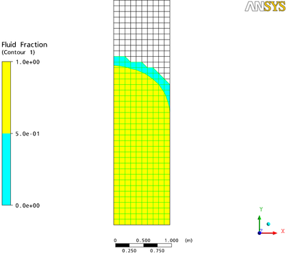
Figure 21.1: 2D VOF Simulation Results displays the  field distribution for a typical 2D VOF simulation that is tracking a
single fluid. Note that the fluid is only determined to be present where the fluid
fraction
field distribution for a typical 2D VOF simulation that is tracking a
single fluid. Note that the fluid is only determined to be present where the fluid
fraction  is above a threshold value of 0.5, which in Figure 21.1: 2D VOF Simulation Results is the region colored yellow. Any
region of the domain where
is above a threshold value of 0.5, which in Figure 21.1: 2D VOF Simulation Results is the region colored yellow. Any
region of the domain where  is 0 (that is, the uncolored region) or below the threshold value (that is,
the region colored blue) is not considered to contain fluid.
is 0 (that is, the uncolored region) or below the threshold value (that is,
the region colored blue) is not considered to contain fluid.