


Some industrial extrusion applications involve the use of conveyor devices. This is typically the case for profiles whose dimensions and weight require such a guiding device. An illustrative example is the rubber tire tread extrusion process: downstream of the die exit, the profile is sustained by a series of rotating conveyor cylinders or by a moving conveyor belt, at a speed that matches the extrusion line speed.
Some geometric details of the conveyor belt or conveyor cylinders are discarded: instead, they are defined in simple geometric terms and by their role in the extrusion process, or more precisely, within the scope of the extrusion model. Since such a device (either a belt or roller) guides the extrudate profile at a given location and at a given speed, it will be described by means of those quantities. On one hand, a conveyor is represented by a plane defined by a point and an outward direction perpendicular to it, that is, oriented towards the extrudate; while a velocity is assigned. On the other hand, a conveyor roller is represented by a cylinder defined by a radius, an axis direction and a point of the axis, while a rotating velocity is assigned; quite obviously, several conveyor rollers can be involved.
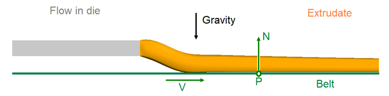
Figure 15.6: An Extrusion Process Involving a Conveyor Belt illustrates a basic extrusion case involving the use of a conveyor belt. As suggested, the conveyor belt is a plane described by a conveniently selected point P, an outward normal direction N to the plane and a velocity V.
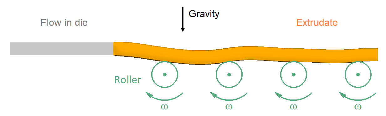
Similarly, Figure 15.7: An Extrusion Process Involving Conveyor Rollers illustrates an extrusion case involving a series of rollers. A conveyor roller is
a cylinder defined by its radius R, a point
P and an axis D passing through this
point, as well as a (signed) angular velocity  around the axis.
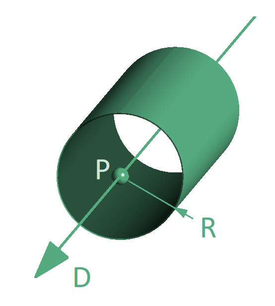
In addition, Figure 15.8: Perspective View of a Roller with Geometric Parameters illustrates the geometric details of the roller.
From the deformation of the extrudate as suggested in both Figure 15.6: An Extrusion Process Involving a Conveyor Belt and Figure 15.7: An Extrusion Process Involving Conveyor Rollers, it is understood that gravity plays a role in the process: the guiding device will prevent further downward deformations. Also, the extrudate is obviously pulled at the end of the computational domain: a velocity must be imposed at the exit section, and this is anyway preferable than imposing a normal force that is a priori unknown. Some guiding devices purposely drag the extrudate, in which case the relative tangential velocity between the extrudate and the device is controlled by a slipping coefficient, after the fashion of the Navier’s slipping law. A frictionless guiding device (for example, an air cushion) is a specific case where the friction coefficient is set to zero.